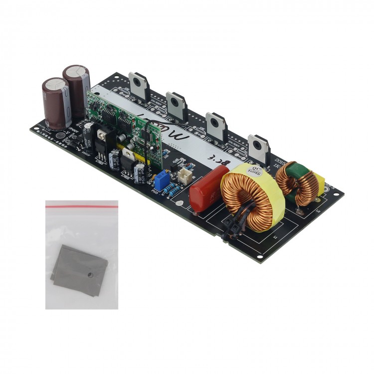
• 1000W Pure Sine Wave Inverter Board Finished Board (without Heat Sink) 220V Output for Amplifier DIY
  • 1000W Pure Sine Wave Inverter Board Finished Board (without Heat Sink) 220V Output for Amplifier DIY
  • 1000W Pure Sine Wave Inverter Board Finished Board (without Heat Sink) 220V Output for Amplifier DIY
  • 1000W Pure Sine Wave Inverter Board Finished Board (without Heat Sink) 220V Output for Amplifier DIY
  • 1000W Pure Sine Wave Inverter Board Finished Board (without Heat Sink) 220V Output for Amplifier DIY
  • 1000W Pure Sine Wave Inverter Board Finished Board (without Heat Sink) 220V Output for Amplifier DIY
  • 1000W Pure Sine Wave Inverter Board Finished Board (without Heat Sink) 220V Output for Amplifier DIY

1000W Pure Sine Wave Inverter Board Finished Board (without Heat Sink) 220V Output for Amplifier DIY

Availability: In stock, usually dispatched in 1 business day

  • Price:$37.51
  • Price in reward points: 375 Reward Points: 4
  • Quantity 3+ units 10+ units 30+ units 50+ units More
    Price /Unit $36.76 $36.01 $34.88 $33.38 Contact US
Quantity:
1000W Pure Sine Wave Inverter Board Finished Board (without Heat Sink) 220V Output for Amplifier DIY

Specifications:

- Product name: Modified sine wave inverter to pure sine wave inverter board
- Input voltage: DC350-DC400V / Optimal input voltage: DC380V
- Input voltage: AC16V (be sure to note that the two sets of voltage inputs must be synchronized)
- Output voltage: AC 220V
- Output frequency: 50HZ/60HZ adjustable
- Output waveform: pure sine wave
- Protection: over-voltage, over-current and over-temperature protection
- Voltage/current/temperature feedback
- Net weight: 262g/0.6lb

Package Included:
- 1 x 1000W Sine Wave Inverter Board Finished without Heat Sink

Attention:
- When the sold board has been soldered tin and used, returns or exchanges are not supported, because the above situation has affected the second sale of the product.

Packaging Details:
- G.W.: 0.4kg

Operation Manual:
The product can change a 1000W modified sine wave inverter to a pure sine wave inverter.

Users first dismantle the power transistors of modified sine wave inverter, and then look at how many modified sine wave inverter transformers there are. And then see whether the secondary circuit of the transformers is connected in parallel or in series, and then increase the transformer parameters. When the transformer secondary coil of modified sine wave inverter is parallel type, each transformer secondary coil is added with 16 turns. When the transformer secondary coil of modified sine wave inverter is of series type, each transformer secondary coil is added with 8 turns. Then add a small voltage parameter to one transformer NC pin of modified wave transformers. The small voltage parameter uses a single 0.6mm copper wire, which is wound 5 times in the transformer, and this small voltage is connected to the AC: 16V position. (Note: Do not disassemble the magnetic ring when adding parameters to the transformer).

After the transformer parameters are added, be sure to change the high-voltage capacitor of the modified wave inverter back to 220UF/450V. Remember: The positive end of the high voltage capacitor of the modified wave inverter has a feedback resistor, which is several hundred K. The resistor also needs to be changed to one with a larger resistance. The voltage of high-voltage capacitor (positive/negative) of the re-energizing test is DC380V. After the test voltage is normal, a connection wire can be used to provide the voltage to the pure sine wave inverter board. The output voltage of the pure sine wave inverter board is AC220V/50HZ, and the output waveform is pure sine wave. Note: The input of two sets of voltages must be synchronized. It is forbidden to input two sets of voltages and cannot use two power supplies to provide voltage, because it will cause the (cold/hot) negative electrode to burn out the product.

Write a review

Note: We will keep it confidential.
Note: HTML is not translated!
 
Captcha