| Quantity | 3+ units | 10+ units | 30+ units | 50+ units | More |
|---|---|---|---|---|---|
| Price /Unit | $42.06 | $41.20 | $39.92 | $38.20 | Contact US |
 STK428-640 HiFi Power Amplifier Board 200Wx2 Class D High Power Amplifier Module PWM CMOS Logic Level Audio Input
$36.49
 OPS200 Dual Operational Amplifier 60mA Class A Op Amp for Low Impedance Circuit Amplifier and Drivers
$15.79
 PAP-HD1-XLR Hi-End Fully Balanced Preamplifier Board Support Remote Control Replacement for HDAM Circuit
$84.53
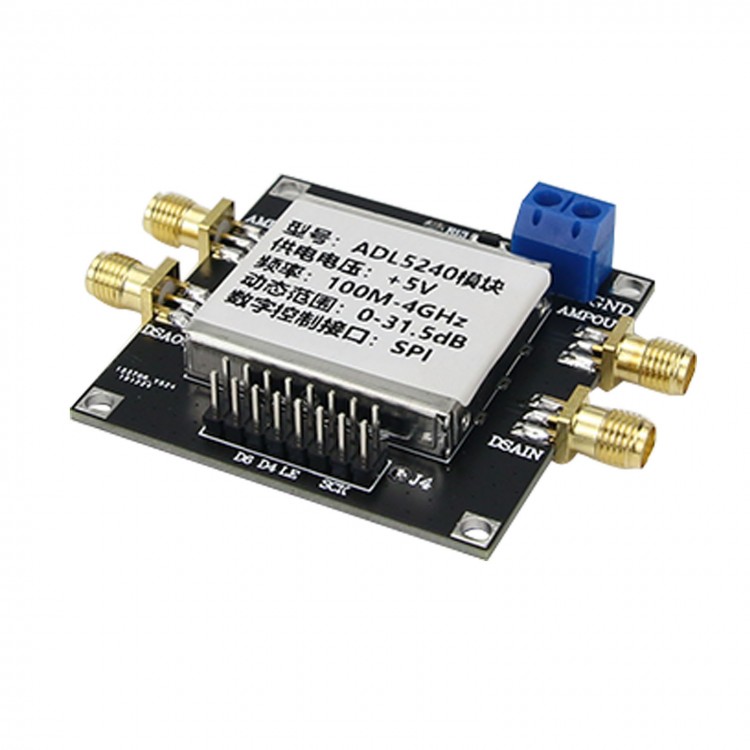
100M-4GHz Variable Gain Amplifier RF IF Digitally Controlled VGA ADL5240 Module
ADL5240:
Description:
The ADL5240 is a high performance, digitally controlled variable gain amplifier (VGA) operating from 100 MHz to 4000 MHz. The VGA integrates a high performance, 20 dB gain, internally matched amplifier (AM P) with a 6-bit digital step attenuator (DSA) that has a gain control range of 31.5 dB in 0.5 dB steps with ±0.25 dB step accuracy. The attenuation of the DSA can be controlled using a serial or parallel interface.Both the gain block and DSA are internally matched to 50 Ω at their inputs and outputs and are separately biased. The separate bias allows all or part of the ADL5240 to be used, which facilitates easy reuse throughout a design. The pin out of the ADL5240 also enables either the gain block or DSA to be first, giving the VGA maximum flexibility in a signal chain. The ADL5240 consumes just 93 mA and operates from a single supply ranging from 4.75 V to 5.25V. The VGA is packaged in a thermally efficient, 5 mm × 5 mm, 32-lead LFCSP and is fully specified for operation from −40°C to +85°C. A fully populated evaluation board is available.
Features:
- Operating frequency: 100 MHz to 4000 MHz (100M to 4GHz )
- Digitally controlled VGA with serial and parallel interfaces
- 6-bit, 0 .5 dB digital step attenuator
- Gain control range: 31.5 dB; Step accuracy: ±0 .2 5 dB
Gain Module Amplifier Specifications:
- Gain: 19.7 dB (2.14 GHz)
- OIP3: 41.0 dBm (2.14 GHz)
- P1dB: 19.5 dBm (2.14 GHz)
- Noise figure: 2.9 dB (2.14 GHz)
- Can set gain module or digital step attenuator as the first
- Powered by single power supply from 4.75 V to 5.25 V
- Low quiescent current: 93 mA
- High heat dissipation performance 5mm x 5mm, 32-pin LFCSP packaging
- The companion ADL5243 integrates a 1/4 W driver amplifier to drive gain module and the output of DSA
Applications:
- Wireless infrastructure
- Automated test equipment
- RF/IF gain control
Module Parameters:
- Power supply: + 5V
- Frequency range: 100MHZ-4GHZ
- Digital control attenuator attenuation range: 0-31.5DB
- Gain of fixed gain amplifier: 20DB
- Flatness and insertion loss: refer to the actual measured S21 parameters
- PCB board layers: four layers; with metal shield box
Package Included:
- 1 x Variable Gain Amplifier
Measured S21 Parameters:
Fixed amplifier measured S21 parameters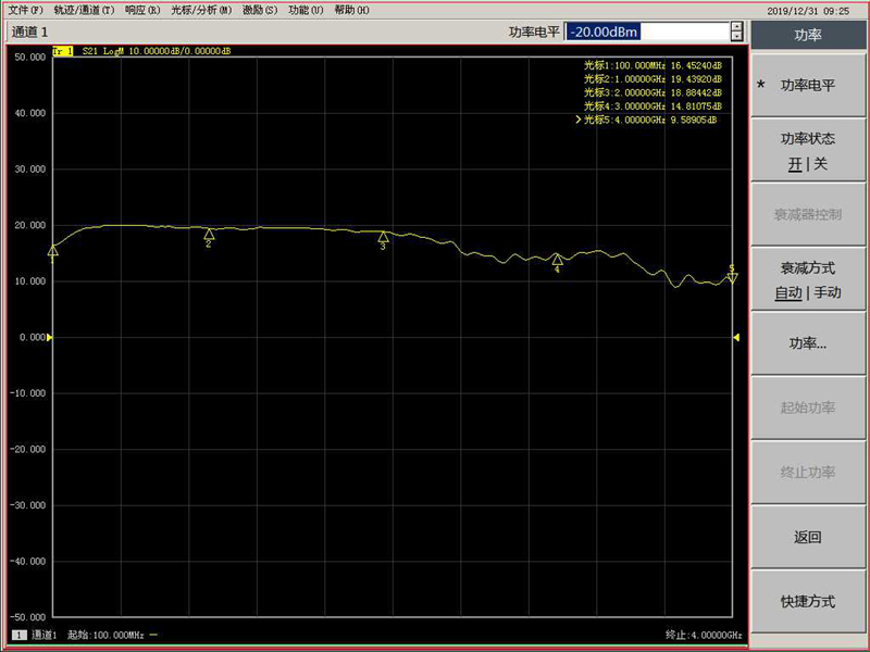
Program-controlled gain attenuator measured S21 parameters (0DB)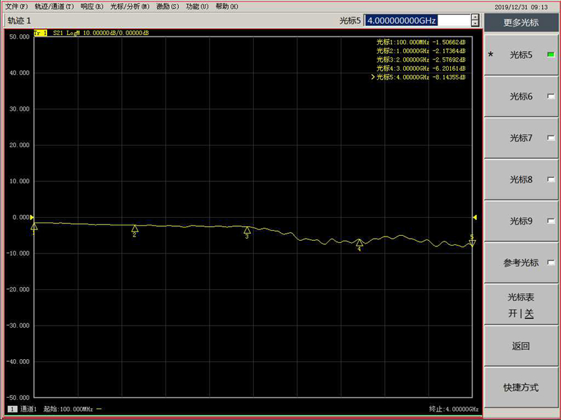
Program-controlled gain attenuator measured S21 parameters (10DB)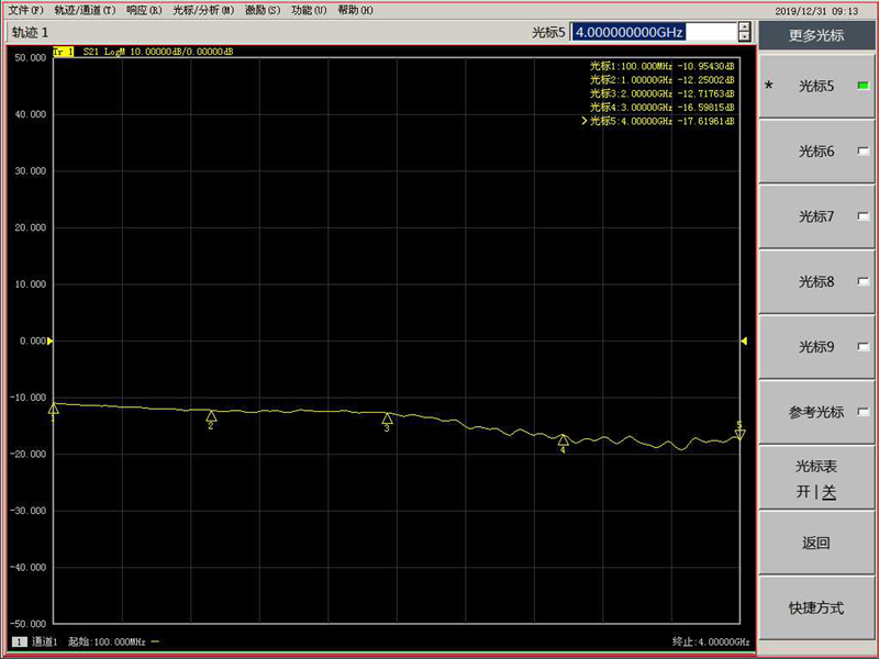
Program-controlled gain attenuator measured S21 parameters (20DB)
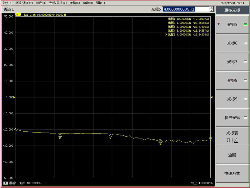
Program-controlled gain attenuator measured S21 parameters (30DB) 
Reference PDF schematic (provided after purchasing)
Parallel and Serial Port Protocol Control:
/*The chip will using GPIO to Init*/
void ADL5240_Init(void)
{
GPIO_InitTypeDef GPIO_InitStruct;
RCC_APB2PeriphClockCmd(RCC_ADL5240 GPIO_ADL5240_L , ENABLE);
#if Communication_Mode
GPIO_InitStruct.GPIO_Pin = GPIO_Pin_ADL5240_CLK GPIO_Pin_ADL5240_DATA;
GPIO_InitStruct.GPIO_Mode = GPIO_Mode_Out_PP;
GPIO_InitStruct.GPIO_Speed = GPIO_Speed_50MHz;
ADL5240_D3_Clr();
ADL5240_D4_Clr();
ADL5240_D5_Clr();
ADL5240_LSB_Set();
GPIO_Init(GPIO_ADL5240,&GPIO_InitStruct);
GPIO_InitStruct.GPIO_Pin = GPIO_Pin_ADL5240_LE;
GPIO_InitStruct.GPIO_Mode = GPIO_Mode_Out_PP;
GPIO_InitStruct.GPIO_Speed = GPIO_Speed_50MHz;
GPIO_Init(GPIO_ADL5240_G,&GPIO_InitStruct);
#else
GPIO_InitStruct.Pin = GPIO_Pin_ADL5240_D1 GPIO_Pin_ADL5240_D2 GPIO_Pin_ADL5240_D3
GPIO_Pin_ADL5240_D4 GPIO_Pin_ADL5240_D5 GPIO_Pin_ADL5240_D6 GPIO_Pin_ADL5240_D0;
GPIO_InitStruct.GPIO_Mode = GPIO_Mode_Out_PP;
GPIO_InitStruct.GPIO_Speed = GPIO_Speed_50MHz;
GPIO_Init(GPIO_ADL5240,&GPIO_InitStruct);
#endif
}
#if Communication_Mode
/* Write a data to ADL5240-serial*/
void ADL5240_Write(uint8_t data)
{
uint8_t i;
//data = 0x7f;
ADL5240_LE_Clr(); //Pull down LE as as staring signal
ADL5240_CLK_Clr();
ADL5240_LE_Set();
delay(10);
ADL5240_LE_Clr(); //Now start to write data
for(i = 0 ; i < 6 ; i ++){
if(data & 0x80)
ADL5240_DATA_Set();
else
ADL5240_DATA_Clr();
ADL5240_CLK_Set();
delay(2);
ADL5240_CLK_Clr();
data <<= 1;
delay(5);
}
// delay(1);
ADL5240_LE_Set();
delay(20);
ADL5240_LE_Clr();
}
#else
/* Write a data to ADL5240-parallel*/
void ADL5240_Write(uint8_t data)
{
if(data & 0x80)
ADL5240_D1_Set();
else
ADL5240_D1_Clr();
data <<= 1;
if(data & 0x80)
ADL5240_D2_Set();
else
ADL5240_D2_Clr();
data <<= 1;
if(data & 0x80)
ADL5240_D3_Set();
else
ADL5240_D3_Clr();
data <<= 1;
if(data & 0x80)
ADL5240_D4_Set();
else
ADL5240_D4_Clr();
data <<= 1;
if(data & 0x80)
ADL5240_D5_Set();
else
ADL5240_D5_Clr();
data <<= 1;
if(data & 0x80)
ADL5240_D6_Set();
else
ADL5240_D6_Clr();
}
#endif