| Quantity | 3+ units | 10+ units | 30+ units | 50+ units | More |
|---|---|---|---|---|---|
| Price /Unit | $89.42 | $87.59 | $84.85 | $81.20 | Contact US |
 Black 3D-Printed Mini ESP32 Marauder Development Board Positioning Module with 1.44-inch Screen
$33.36
Black 3D-Printed Mini ESP32 Marauder Development Board Positioning Module with 1.44-inch Screen
$33.36
 White 3D-Printed Mini ESP32 Marauder Development Board Positioning Module with 1.44-inch Screen
$33.36
White 3D-Printed Mini ESP32 Marauder Development Board Positioning Module with 1.44-inch Screen
$33.36
 Black Shell T-Embed-CC1101 Plus ESP32-S3 Development Board NRF24L01 2.4GHz ISM Transceiver with 1.9-inch LCD
$88.55
Black Shell T-Embed-CC1101 Plus ESP32-S3 Development Board NRF24L01 2.4GHz ISM Transceiver with 1.9-inch LCD
$88.55
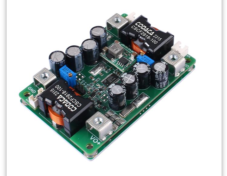
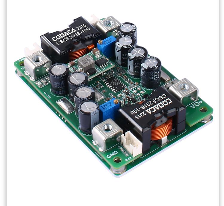
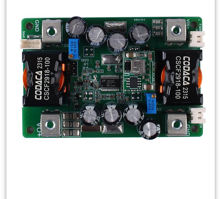
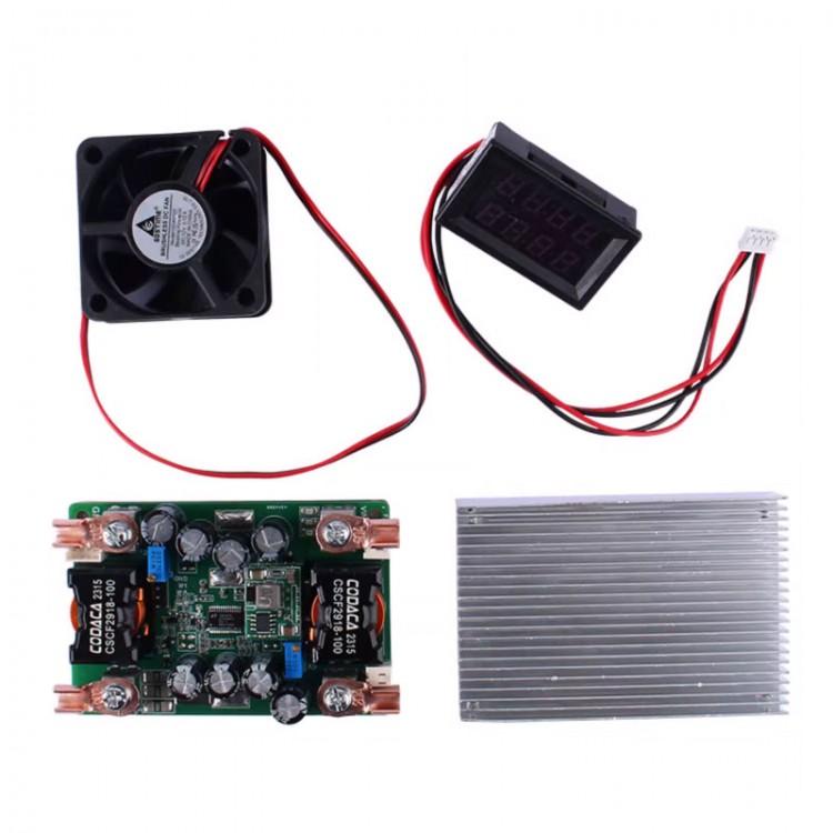
2000W DC12-56V to DC2-54V Step-down Power Module Set DC-DC Buck Converter+Auxiliary Power Board+Heat Dissipation Kit+Display
Precaution:
- Please make sure that you have certain ability for power testing and measurement and equipment. Do not test this power supply with a laboratory 3A adjustable voltage regulator. First, figure out what kind of output you need, and then determine what input parameters you need to provide.
- Do not test the current limiting power supply using the CC mode of electronic loads.
- The meaning of the output current adjustment range is: under sufficient input power, if the output power supply is 20V and a 0.4ohm resistor is connected to adjust the CC potentiometer, the output current can only be adjusted within a range of minimum to maximum 50A, and cannot be adjusted to the minimum limit value (excluding 0A).
- High cost performance DC-DC step-down with adjustable output voltage and current, LED constant current, battery charging.
- Attention: Non-isolated BUCK power supplies will backflow, and the intermittent mode DCM of the power supply allows backflow to the output end, resulting in a small static current. If the input end can accept backflow, it can be left untreated.
- Expandable functions: External enable control to turn off power, output current controlled and regulated by 0-3V DC signal of microcontroller AD, input and output current detection signal analog output.
Features:
- Non-isolated synchronous switch buck-boost
- Wide input DC12-58V, output DC2-54V
- Peak efficiency up to >98%
- Remote on/off, over-temperature protection, optional temperature controlled fan
- Constant current indicator light; work indicator light; adjustable output voltage and current, externally controllable; optional voltage and current display; high voltage stabilization accuracy; ultra fast transient response
- High thermal conductivity design of aluminum substrate, convenient MEI prediction for constant frequency operation.
- The power can reach over 1KW (input and output > 24V).
- No special specifications, all tests are conducted at 24V input voltage, pure resistive load, and 25°C room temperature. Any changes are not notified separately.
Absolute Maximum Ratings:
- Input voltage: -1 ~ 60V (constant)
- Output voltage: -1 ~ 60V
- Power shutdown interface EN: 0.7 ~ 30V
- External voltage control interface: 0 ~ 5V
- External current control interface: 0 ~ 5V
- Fan interface current limit (optional): 0.3A
- Aluminum substrate and power pin withstand voltage: ≤500V (typ. 300V) (non-isolated)
- Maximum torque of screw terminals: 1 - 2N.m
- Potentiometer rotation life: 200 rotation
- Storage temperature: -45℃ ~ 125℃
Recommended Using Parameters:
- Input voltage: 12 - 56V
- Input current: ≤30A (typ. 20A)
- Output voltage: 1 - 52V
- Output current: ≥0A (typ. 40A)
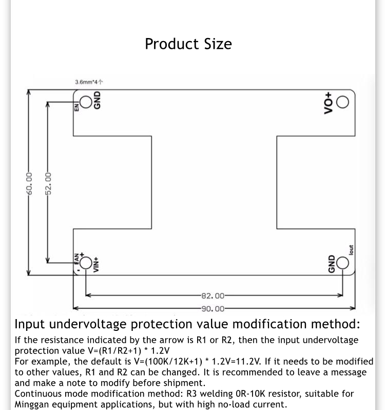
Input Parameters:
- Input working voltage range: 11.2V-58V
- Input undervoltage protection adjustable range: 6 - 56V (typ. 11.2V) (can modify the VIN=6V, VO=2-5V)
- Undervoltage protection hysteresis value: 0.96*Vu - 1.04*Vu (typ. Vu) (Vu is the setting undervoltage value)
- Input current working range: ≤40A (typ. 20A)
- Input fuse melting current: ≤80A (typ. 60A)
- Input current limit value (short time): typ. 50A
- Empty input current value: 8 - 12mA (typ. 11mA) (constant mode)
- Shutdown current (complete machine shutdown): 0.1 - 0.3mA (typ. 0.2mA)
- Input & output voltage difference (lout=40A): 0.6 - 1A (typ. 0.8A) (it is recommended to use it for 2V above)
Output Parameters:
- Output voltage range: 1.5 - 55V
- Operating range of output current: ≤50A (typ. 40A) (Vo < 24V can work at 50A)
- Output current regulation range: 0/16 - 52A
- Output current limit: ≤52.5A (typ. 52A)
- Load adjustment rate: -0.1 to -0.3% (typ. -0.2%)
- Constant current and constant voltage switching voltage drop value: -0.5 to -1.0V (typ. -0.6V)
- Output voltage ripple noise PK-PK: 15 - 60mA (typ. 00mA) (48V step down to 24V/45A)
- Output voltage ripple noise PK-PK: 20 - 45mA (typ. 30mA) (48V step-down to 12V/50A)
Dynamic Parameters:
- Load step Vo=24V/45A: 0.8 - 1V (typ. 0.9V) (10% - 100% lout)
- Recovery time: ≤0.45ms (typ. 0.3ms) (<2% Vout)
- Output voltage overshoot: 0.4 - 0.65V (typ. 0.6V) (load 100%-10%)
- Recovery time: ≤0.35ms (typ. 0.3MS) (<2% Vout)
- Start time: ≤52ms (typ. 50ms) (power-on to voltage output established)
- Output slow start time: ≤24MS (typ. 20MS)
Conversion Efficiency:
- 48V to 36V (1.3KW): 97.8% - 98.1% (typ. 98%)
- 48V to 24V (1.1KW): 96.8% - 97.1% (typ. 97%)
- 48V to 12V (0.45KW): 96% - 96.2% (typ. 96.1%)
Other Parameters:
- Switching frequency: 215KHz - 225KHz (typ. 220KHz)
- Recommended boost voltage difference ratio: up to 15X (typ. 4X) (Vo/Vin)
- Voltage display accuracy: ≥0.5% (typ. 1%) (optional)
- Current display accuracy: 0.3 - 1% (typ. 0.5%) (optional)
- EN enables the effective voltage to be turned off: 0 - 1V (typ. 0.7) (EN off < 0.7V)
- ACC controls the effective voltage at startup: 5 - 28V (optocoupler isolation control)
- Vo external control effective voltage: 0 - 1.7V
- Voltage control signal load capacity: ≥2mA (typ. 5mA) ((the potentiometer needs to be turned counterclockwise to the bottom)
- Lout external control effective voltage: 0 - 1.5V
- Current control signal load capacity: ≥5mA (typ. 10mA) (the potentiometer needs to be turned clockwise to the bottom)
- Fan terminal voltage (optional): 11.5 - 12.0V (typ. 11.7V) (Vin > 14V)
- Fan terminal supply current (optional): ≤0.4A (typ. 0.3A) (Vin > 14V)
- Temperature controlled fan power-on value: 50 - 60℃ (typ. 55℃)
- Over temperature protection value: ≤95℃ (typ. 85℃) (aluminum board temperature)
- Power supply operating temperature: -45 to 85℃ (typ. 25℃)
- Main controller operating temperature: ≥-45℃ (typ. 125℃)
- Temperature resistance of electrolytic capacitors during operation: 105℃
- Storage temperature: -20 to 85℃ (typ. 25℃)
- Cooling method: natural cooling within 10W loss; adding cooling fan within 15W loss or forced air cooling for 20W loss above) (environmental temperature: 25℃)
- Size: 110 x 90 x 21mm
- Net weight: 170g
- Optional cooling fan weight & size: 140g; 90 x 60 x 18mm
- Note:
1: When the output is a resistive load (resistance, LED), the output current cannot be adjusted to within 16A, and there is a minimum requirement. When the output is used to charge the battery, the current can be adjusted from 0. Or specially modify it to the lower limit current value.
2: The default intermittent mode can be connected to the battery for charging. It is also recommended to add an ideal diode and set a good input undervoltage protection value to prevent the output voltage from flowing back to the input end. It can be modified to continuous mode operation (with good dynamic response, low ripple and interference, suitable for sensitive devices such as speakers).
3: When working for a long time with an output current of 50A and only outputting less than 24V, other high output voltages need to be reduced by 20-30%.
4: The situation where the startup time needs to be adjusted is when the input power has a long startup time. For example, if the AC adapter outputs a full load voltage for 50ms to establish, and the startup time of this power supply is 20ms, it may cause the AC to be unable to start normally with load. It is recommended to power on first before conducting load testing, or contact to modify the startup time.
5: When switching between constant voltage and constant current, there will be a deviation of 0.5-1V during the constant voltage stage. For example, if the no-load voltage is 29.4V and the current limit is set to 20A, the output voltage will be less than 28.7V, and the current will remain constant at 20A (-5%). The current between 28.8-29.0V may be 18-15A, and the internal resistance of the wire and battery will have a certain impact. The constant voltage mode is based on the load adjustment rate.
6: Some parameters may need to be adjusted for different applications.

Interface Introduction:
- VIN+: Power input positive pole; NPUT+. Can not be connected to AC, no reverse connection allowed.
- GND: Power input/output negative pole; Public negative electrode.
- VO+: Power output positive pole; it is recommended to use parallel connection of multiple terminals for high power.
- RX1: Output voltage regulation, increasing clockwise; 25 turns of the potentiometer correspond to a change in output voltage of 1.5-55V, and the VO should not be connected to a voltage of 36V or above in a counterclockwise direction.
- RX2: Output current regulation, increasing clockwise; 25 rotations of the potentiometer correspond to a change in output current of 0-52A. Only charging the battery can start from 0 and adjust the resistance load range from 16-52A. The specific current limit value needs to be measured in practice.
- P1: 12V/0.3 Temperature-controlled fan power supply port; The fan turns on and off as the temperature changes.
- P2: EN enable port (left PIN is EN; right is GND); After the interface is pulled down to GND, the entire power supply is turned off, including the auxiliary power supply. The anti-interference ability of this interface is relatively weak, and it is recommended to only use it when pulled down, and the wiring should not be close to the interference source.
- P3: Optional output voltage/current port; After configuration, the output voltage value of the entire working range can be displayed. After configuration, the actual output current value can be displayed, and the signal value can also be output for microcontroller inspection (rightmost pin) Vi=0.03*lout. For example, if the output current is 50A, the pin voltage will be changed to 1.5V.
- P4-1: Controlling signal GND; Connect the negative pole of the control signal.
- P4-2: The output current external control interface (right signal interface); After inputting an analog voltage of 0-1.5V, the output current limit value can be controlled to change from 0/16-50A, and RX2 needs to be adjusted clockwise to the end. The control signal needs to have a certain load capacity.
- P4-3: The output voltage external control interface (left signal interface); RX1 first adjusts the output voltage to 28V, and then connects a 0-1.7V analog voltage signal to control the output voltage to change from 56-0.8V, which is an inverse proportional control. Signal lines should avoid approaching interference sources.
- LED1: Output status indicator light; When the output is in short circuit protection, over temperature protection, output current limiting, and actual output voltage deviation are ± 10%, the light will be on.
- LED2: 12V auxiliary power supply indicator light; If the auxiliary power supply is normal, the light will be on, and the VIN needs to be>14V.
Note:
1: Testing this power supply must ensure that the input source can provide sufficient current (>50A) to ensure that the power supply does not collapse or even be damaged, especially when starting on load.
2: The startup time of the input source must be less than the startup time of the local power supply (such as the adapter as input), otherwise it may not be able to start with load.
3: The input wire connected to this power supply must not be too long (the internal resistance of the wire must not be too high), otherwise the power supply may cause vibration and abnormalities.
4: If there is a diode connected in series from the input source to the power supply, the power supply may be damaged due to surge voltage caused by instantaneous connection and shutdown (BOOST effect of the line). Long wires should ensure that the input voltage is used below 50V, leaving enough margin.
5: Do not use the CC mode of electronic loads as the load of this power supply. It is recommended to use the CR mode. CC mode absorbs current, this power supply has current limit, and in a constant current state, it will cause the power supply to crash.
6: Suggest adjusting the output voltage to connect a small current resistor load (false load) to ensure real-time adjustment of the output voltage potentiometer, otherwise the output voltage changes slowly; The adjustment value is not accurate.
7: The current limiting value shall be set in resistance CR mode or battery with less than 60% charge. For example, first set the no-load voltage of 29.4V, then set the current limiting value of 20A, then the load resistance of 29.4*0.6/20A<R<29.4*0.8/20A is 0.88Ω~1.17Ω, and the 1Ω resistance can be selected, and then adjust the potentiometer until the output current is 20A.
Package Included:
- 1 x Power Module
- 1 x Auxiliary Power Board
- 1 x Cooling Fan
- 1 x Radiator
- 1 x Display Module