| Quantity | 3+ units | 10+ units | 30+ units | 50+ units | More |
|---|---|---|---|---|---|
| Price /Unit | $64.88 | $63.55 | $61.57 | $58.92 | Contact US |
 Black 3D-Printed Mini ESP32 Marauder Development Board Positioning Module with 1.44-inch Screen
$33.36
Black 3D-Printed Mini ESP32 Marauder Development Board Positioning Module with 1.44-inch Screen
$33.36
 White 3D-Printed Mini ESP32 Marauder Development Board Positioning Module with 1.44-inch Screen
$33.36
White 3D-Printed Mini ESP32 Marauder Development Board Positioning Module with 1.44-inch Screen
$33.36
 Black Shell T-Embed-CC1101 Plus ESP32-S3 Development Board NRF24L01 2.4GHz ISM Transceiver with 1.9-inch LCD
$88.55
Black Shell T-Embed-CC1101 Plus ESP32-S3 Development Board NRF24L01 2.4GHz ISM Transceiver with 1.9-inch LCD
$88.55
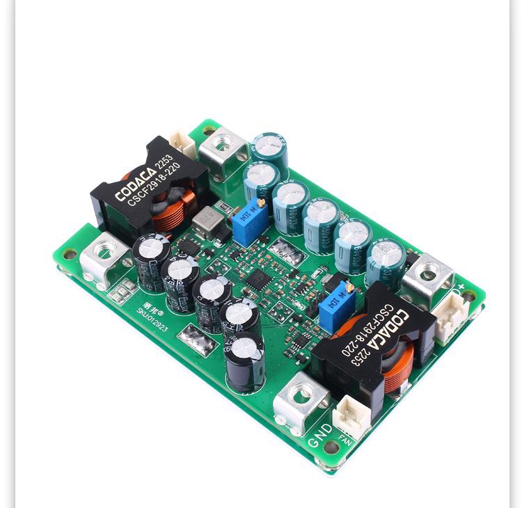
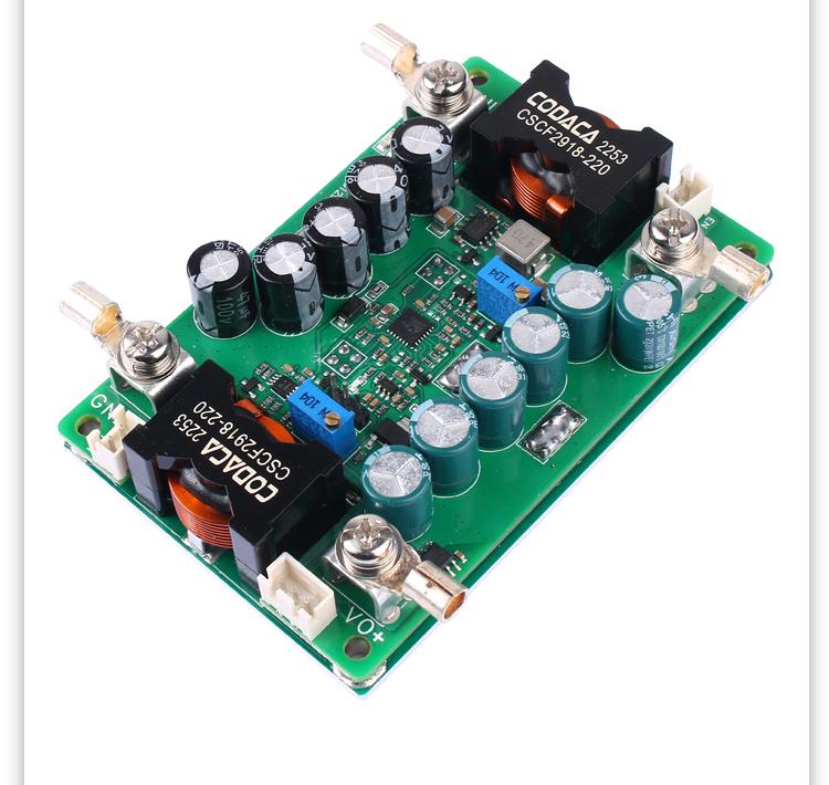
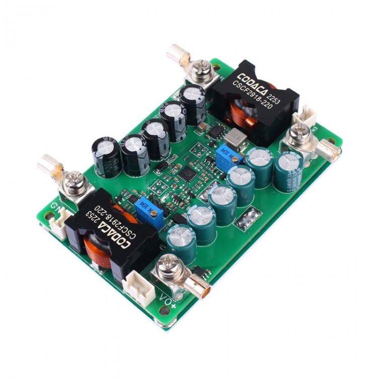
2800W High Power DC14-90V to DC18-140V Boost Power Supply Module Constant Voltage and Current DC-DC Boost Converter
Precaution:
- Please make sure that you have certain ability for power testing and measurement and equipment. Do not test this power supply with a laboratory 3A adjustable voltage regulator. First, figure out what kind of output you need, and then determine what input parameters you need to provide.
- Do not test the current limiting power supply using the CC mode of electronic loads.
- The meaning of the output current adjustment range is: under sufficient input power, if the output power supply is 20V and a 0.4ohm resistor is connected to adjust the CC potentiometer, the output current can only be adjusted within a range of minimum to maximum 50A, and cannot be adjusted to the minimum limit value (excluding 0A).
- Attention: Non-isolated BUCK power supplies will backflow, and the intermittent mode DCM of the power supply allows backflow to the output end, resulting in a small static current. If the input end can accept backflow, it can be left untreated.
- Expandable functions: External enable control to turn off power, output current controlled and regulated by 0-3V DC signal of microcontroller AD, input and output current detection signal analog output.
Features:
- Non-isolated boost power supply
- Wide input DC14-90V, output DC18-140V
- Peak efficiency up to > 96.0%
- Adjustable output voltage and current
- Working indicators, the output voltage and current are externally controllable (potentiometer needs to be removed), with high voltage difference ratio and automatic input current output reduction. It can be charged by the battery and has reverse charging protection up to 150V.
- Low static current, high voltage regulation accuracy, and constant frequency operation make MEI easy to predict.
- The power can reach over 1KW (input and output > 48V).
- No special specifications, all tests are conducted at 48V input voltage, pure resistive load, and 25°C room temperature. Any changes are not notified separately.
Absolute Maximum Ratings:
- Input voltage: -1 ~ 95V (constant)
- Output voltage: -1 ~ 150V
- Power shutdown interface EN: 0.7 ~ 30V
- Fan interface current limit (optional): 0.35A
- Aluminum substrate and power pin withstand voltage: ≤500V (typ. 300V) (non-isolated)
- Maximum torque of screw terminals: up to 2N.m (typ. 1N.m)
- Potentiometer rotation life: 200 rotation
- Storage temperature: -45℃ ~ 125℃
Recommended Using Parameters:
- Input voltage: 24 - 72V (typ. 48V)
- Input current: 0 - 30A (typ. 25A)
- Output voltage: 48 - 120V
- Output current: ≤ 15A (typ. 10A)
Input Parameters:
- Input working voltage range: 9.0V-58.0V
- Input undervoltage protection adjustable range: 6.0 - 50.0V (typ. 9.0V)
- Undervoltage protection hysteresis value: 0.9*Vu - 1.1*Vu (typ. Vu) (Vu is the setting undervoltage value)
- Long time working maximum input current: ≤ 20.5A (typ. 20.0A)
- Input current limit value (short time): ≤ 20.5A (typ. 20.3A)
- Empty input current value: 45 - 150mA (typ. 60mA)
- Shutdown current (complete machine shutdown): 0.2 - 0.4mA (typ. 0.3mA)
- Input & output voltage difference (lout=40A): 0.6 - 1A (typ. 0.8A) (it is recommended to use it for 2V above)
Output Parameters:
- Output voltage range: 18 - 140V (support desktop PC device power supply)
- Output current working range: ≤ 15A (typ. 10A)
- Output current regulation range: ≤20A (need ensure VO=VIN > 5V)
- Output current limit: typ. 20A (do not short circuited)
- Load adjustment rate: -0.1 to -0.2% (typ. -0.12%)
- Output voltage ripple noise PK-PK: 380 - 550mA (typ. 420mA) (48V boost 96V/1200W)
Dynamic Parameters:
- Load step 48V-96V/1.2KW: 8 - 9.5V (typ. 8.2V) (0% - 100% lout)
- Recovery time: typ. 0.5ms (<2% Vout)
- Load step 48V-96V/1.2KW: 2 - 3.5V (typ. 2.2V) (10% - 100% lout)
- Recovery time: typ. 0.3MS (<2% Vout)
- Output voltage overshoot: 2.6 - 3.0V (typ. 2.8V) (load 100% - 0%)
- Recovery time: 1 - 3MS (typ. 2MS) (<2% Vout)
- Start time: ≤ 5ms (typ. 4ms) (power-on to voltage output established)
Conversion Efficiency:
- 48V to 96V (1.2KW): 96.8% - 97.1% (typ. 97.05%)
- 48V to 140V (1.2KW): 96.0% - 96.4% (typ. 96.2%)
Other Parameters:
- Switching frequency: 165KHz - 175KHz (typ. 170KHz)
- Recommended boost voltage difference ratio: up to 3X (typ. 2X) (Vo/Vin)
- 50% reduction in differential pressure ratio: 3 - 6X (typ. 5X) (Vo/Vin)
- EN enables the effective voltage to be turned off: 0 - 1V (typ. 0.7)
- Temperature controlled fan power-on value: ≤55℃ (typ. 50℃) (aluminum board temperature)
- Over temperature protection value: ≤95℃ (typ. 90℃) (aluminum board temperature)
- Power supply operating temperature: -45 to 85℃ (typ. 25℃)
- Main controller operating temperature: ≥-45℃ (typ. 125℃)
- Temperature resistance of electrolytic capacitors during operation: 105℃
- Storage temperature: -20 to 85℃ (typ. 25℃)
- Cooling method: natural cooling within 10W loss; adding cooling fan within 15W loss or forced air cooling for 20W loss above) (environmental temperature: 25℃)
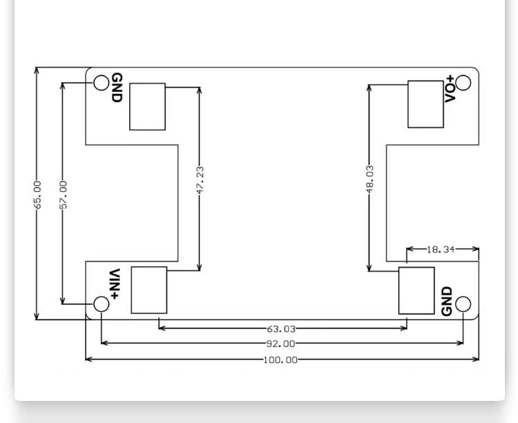
- Size: 100 x 65 x 21mm
- Net weight: 170g
Note:
- Please add a high-capacity LC filter circuit (not included) for inductive or high-capacity loads.
- It can be charged with a battery (battery is not included). It is recommended to adjust the output voltage correctly before connecting to the target battery. Charging between the same voltage level is not allowed.
- The slow start time is the same as the EN enable control delay time. The situation where the output slow start time needs to be adjusted is when the input source startup time is longer. For example, if the AC adaptation output full load voltage establishment time is 50ms, and the power supply startup time is 2ms, it may cause the AC to fail to start normally with load.
- The boost power supply cannot completely disconnect the input and output. After the power supply stops working, VO=VIN.
- If the voltage difference ratio is greater than 3 times, the maximum input current will be limited to around 25A, and if the internal voltage difference ratio is more than 2 times, it is 34A.
- There are electrolytic capacitors in the input and output. If the input voltage is above 48V, it is recommended to use EN shutdown or output positive pole with neutral switch.
- Some parameters may be adjusted for different applications.

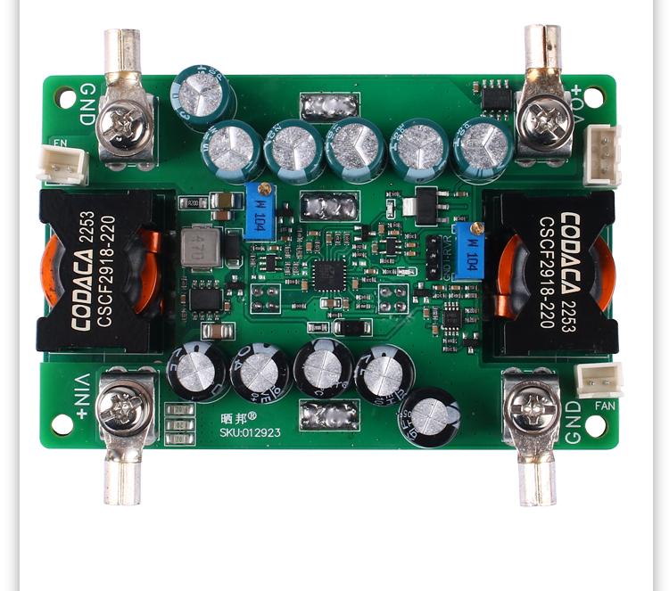
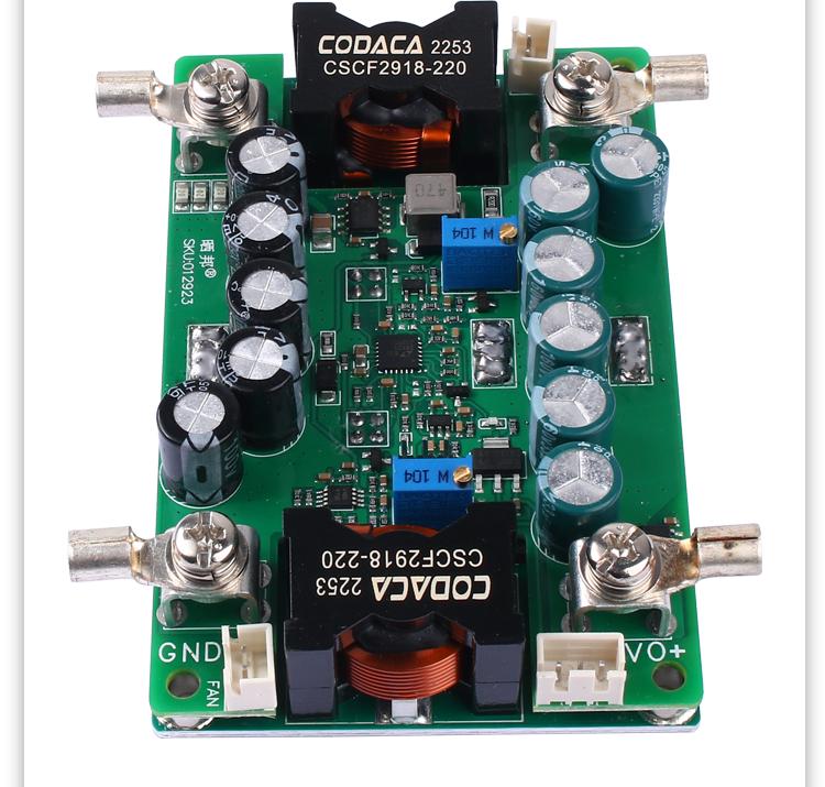
Interface Introduction:
- VIN+: Power input positive pole; INPUT+. Can not be connected to AC, no reverse connection allowed.
- GND: Power input/output negative pole; Public negative electrode.
- VO+: Power output positive pole; it is recommended to use parallel connection of multiple terminals for high power.
- RX1: Output voltage regulation, increasing clockwise; 25 turns of the potentiometer correspond to a change in output voltage of 15-140V (VO>VIN), The specific current limit value needs to be measured in practice, and it should be noted that VO-VIN needs to be greater than 5V, otherwise it cannot be limited.
- RX2: Output current regulation, increasing clockwise; 25 rotations of the potentiometer correspond to a change in output current of 0-20A. The specific current limit value needs to be measured in practice, and it should be noted that VO-VIN needs to be greater than 5V, otherwise it cannot be limited.
- P1: 12V Temperature-controlled fan power supply port; left is +, right is -. The current should not exceed 0.3A and there should be no short circuit. After a short circuit, the power supply will not work.
- P2: EN enable port; after short circuiting, the power supply stops working and only stops boosting. At this moment, the output is equal to the output voltage.
- P3: Optional digital display voltage meter port (not included); for output voltage display.
- P4-1: Controlling signal GND; Connect the negative pole of the control signal.
- LED1: Working indicator green light; light on when it is powered on; light off may be due to undervoltage or malfunction.
- LED2: Current limit indicator: light up when the output reaches the current limit value.
Note:
1: Testing this power supply must ensure that the input source can provide sufficient current (> 35A) to ensure that the power supply does not collapse or even be damaged, especially when starting on load.
2: The startup time of the input source must be less than the startup time of the local power supply (such as the adapter as input), otherwise it may not be able to start with load.
3: The input wire connected to this power supply must not be too long (the internal resistance of the wire must not be too high), otherwise the power supply may cause vibration and abnormalities.
4: If there is a diode connected in series from the input source to the power supply, the power supply may be damaged due to surge voltage caused by instantaneous connection and shutdown (BOOST effect of the line).
5: Do not use the CC mode of electronic loads as the load of this power supply. It is recommended to use the CR mode. CC mode absorbs current, this power supply has current limit, and in a constant current state, it will cause the power supply to crash.
6: Suggest adjusting the output voltage to connect a small current resistor load (false load) to ensure real-time adjustment of the output voltage potentiometer, otherwise the output voltage changes slowly; The adjustment value is not accurate.
7: The control voltage signal 0. -2.4V corresponds to 140V-VIN, and the control current signal 2.5-5V corresponds to 0.20A. Please contact us for instructions on how to use them.
Package Included:
- 1 x Power Module