| Quantity | 3+ units | 10+ units | 30+ units | 50+ units | More |
|---|---|---|---|---|---|
| Price /Unit | $89.47 | $87.65 | $84.91 | $81.26 | Contact US |
 QCC5125 Bluetooth5.1 AK4493SEQ Lossless Audio Decoder Board Wireless Audio Receiver Support for LDAC/APTX HD
$43.35
QCC5125 Bluetooth5.1 AK4493SEQ Lossless Audio Decoder Board Wireless Audio Receiver Support for LDAC/APTX HD
$43.35
 M5Stick T-Lite Online Detection Thermal Imager Acquisition Temperature Measurement Device Development Board IR Imaging Sensor
$102.43
M5Stick T-Lite Online Detection Thermal Imager Acquisition Temperature Measurement Device Development Board IR Imaging Sensor
$102.43
 Thermal Imaging Camera HD256 9.7 Thermal Imager 256x192 Type-C Vanadium Oxide Detector for Motherboard Maintenance
$177.17
Thermal Imaging Camera HD256 9.7 Thermal Imager 256x192 Type-C Vanadium Oxide Detector for Motherboard Maintenance
$177.17
3000W DC9-58V to DC3-56V DC-DC Automatic Step-down Power Supply Module Adjustable Constant Voltage/Current Charging Module
Precaution:
- Please make sure that you have certain ability for power testing and measurement and equipment. Do not test this power supply with a laboratory 3A adjustable voltage regulator. First, figure out what kind of output you need, and then determine what input parameters you need to provide.
- Do not test the current limiting power supply using the CC mode of electronic loads.
- The meaning of the output current adjustment range is: under sufficient input power, if the output power supply is 20V and a 0.4ohm resistor is connected to adjust the CC potentiometer, the output current can only be adjusted within a range of minimum to maximum 50A, and cannot be adjusted to the minimum limit value (excluding 0A).
- High cost performance DC-DC step-down with adjustable output voltage and current, LED constant current, battery charging.
- Attention: Non-isolated BUCK power supplies will backflow, and the intermittent mode DCM of the power supply allows backflow to the output end, resulting in a small static current. If the input end can accept backflow, it can be left untreated.
- Expandable functions: External enable control to turn off power, output current controlled and regulated by 0-3V DC signal of microcontroller AD, input and output current detection signal analog output.
Features:
- Non-isolated synchronous switch buck-boost
- Wide input DC9-58V, output DC3-56V
- Peak efficiency up to >98%
- Overcurrent protection and short circuit protection self recovery
- Remote on/off, over-temperature protection, optional temperature controlled fan constant current indicator light.
- The output voltage and current are adjustable, and the external controllable input voltage tracking function is suitable for fuel cells. The optional output voltage and current digital display meter is suitable for battery charging and backflow protection up to 60V super-capacitor 0 voltage constant current charging.
- Low static current, high voltage stabilization accuracy, constant frequency operation MEI for easy prediction, and optional low EMI spread frequency modulation mode.
- The power can reach over 1KW (input and output > 24V).
- No special specifications, all tests are conducted at 24V input voltage, pure resistive load, and 25°C room temperature. Any changes are not notified separately.
Absolute Maximum Ratings:
- Input voltage: -1 ~ 60V (constant)
- Output voltage: -1 ~ 60V
- Power shutdown interface EN: 0.7 ~ 30V
- External voltage control interface: 0 ~ 5V
- External current control interface: 0 ~ 5V
- Fan interface current limit (optional): 0.35A
- Aluminum substrate and power pin withstand voltage: 300 - 500V (non-isolated)
- Maximum torque of screw terminals: 1 - 2N.m
- Potentiometer rotation life: 200 rotation
- Storage temperature: -45℃ ~ 125℃
Recommended Using Parameters:
- Input voltage: 12 - 56V
- Input current: 0 - 50A
- Output voltage: 3 - 56V
- Output current: 10 - 50A
Input Parameters:
- Input working voltage range: 9.0V-58.0V (it can be modified to 5V)
- Input tracking voltage regulation range: 10V - 56V
- Minimum output current during input tracking: 2 - 6A (typ. 5A) ((not suitable for low input power tracking)
- Input undervoltage protection adjustable range: 5 - 50V (typ. 9V)
- Undervoltage protection hysteresis value: 0.98*Vu - 1.02*Vu (typ. Vu) (Vu is the setting undervoltage value)
- Input current working range: u≤58A (typ. 50A)
- Input current limit value (short time): up to 64A (typ. 62A)
- Empty input current value: 1 - 5mA (4.5mA) (excluding the auxiliary power supply board)
- Shutdown current (complete machine shutdown): 0.03 - 0.4mA (typ. 0.06mA)
Output Parameters:
- Output voltage range: 2.4 - 56V
- Operating range of output current: ≤59.5A (typ. 50A)
- Output current regulation range: 0 - 59.5A (typ. 6A) (minimum current value need to be larger than 6A)
- Output current limit: ≤59.5A
- Load adjustment rate: -0.3 to -0.8% (typ. -0.62%)
- Constant current and constant voltage switching voltage drop value: -0.5 to -1.0V (typ. -0.6V)
- Output voltage ripple noise PK-PK: 150 - 240mA (typ. 180mA) (24V step up to 48V/1.2KW)
- Output voltage ripple noise PK-PK: 40 - 60mA (typ. 50.6mA) (48V step-down to 24V/1KW)
- Output terminal absorbs current (shutdown): 0.08 - 0.4mA (typ. 0.2mA)
Dynamic Parameters:
- Load step 24V-24V/24A: 9.2 - 9.8V (typ. 9.5V) (10% - 100% lout)
- Recovery time: 1.5MS (<2% Vout)
- Output voltage overshoot: 1.2 - 2.0V (typ. 1.8V) (load 100%-0%)
- Recovery time: 160 - 240MS (typ. 200MS) (<2% Vout)
- Start time: ≤4.5MS (typ. 4MS) (power-on to voltage output established)
- Output slow start time (0-24V): ≤1.5MS (typ. 1.2MS)
Conversion Efficiency:
- 24V to 48V (1.2KW): 97.8% - 98.1% (typ. 98%)
- 48V to 48V (2.3KW): 98.3% - 98.7% (typ. 98.5%)
- 48V to 24V (1.1KW): 96.8% - 97.1% (typ. 97%)
Other Parameters:
- Switching frequency: 195KHz - 205KHz
- Recommended boost voltage difference ratio: up to 3X (typ. 2X) (Vo/Vin)
- 50% reduction in rating (lin) voltage difference ratio: 3X - 6X (typ. 5X) (Vo/Vin)
- Buck voltage difference ratio: up to 15X (typ. 2X)
- EN enables the effective voltage to be turned off: 0 - 1V (typ. 0.7) (EN off has the top priority)
- ACC controls the effective voltage at startup: 5 - 28V (optocoupler isolation control)
- Vo external control effective voltage: 0 - 2V
- Voltage control signal load capacity: ≥5mA (typ. 10mA) (need to regulate the voltage within 28V)
- Lout external control effective voltage: 0 - 1.2V
- Current control signal load capacity: ≥1mA (typ. 5mA) (the potentiometer needs to be turned clockwise to the bottom)
- Fan terminal voltage (optional): 11.5 - 12.2V (typ. 11.7V) (Vin > 14V)
- Fan terminal supply current (optional): 0.5 - 0.3A (typ. 0.25A) (Vin > 14V)
- Temperature controlled fan power-on value: ≤55℃ (typ. 50℃) (aluminum board temperature)
- Over temperature protection value: ≤95℃ (typ. 90℃) (aluminum board temperature)
- Power supply operating temperature: -45 to 85℃ (typ. 25℃)
- Main controller operating temperature: ≥-45℃ (typ. 125℃)
- Temperature resistance of electrolytic capacitors during operation: 105℃
- Storage temperature: -45 to 85℃ (typ. 25℃)
- Cooling method: natural cooling within 10W loss; adding cooling fan or forced air cooling for 10W above loss) (environmental temperature: 25℃)
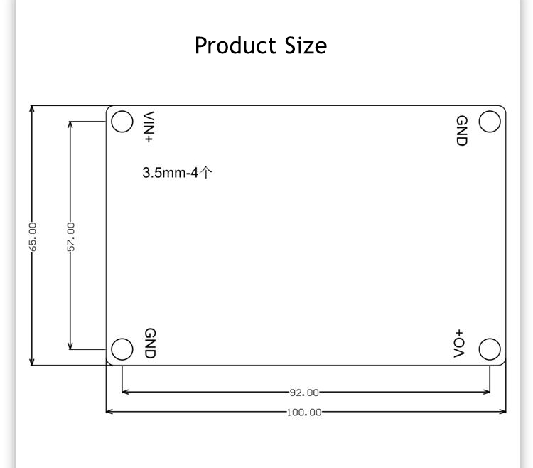
- Size: 100 x 65 x 21mm
- Net weight: 180g
- Optional cooling fan weight & size: 140g; 105 x 70 x 15mm
- Note:
1: The ripple current of the boost output capacitor is high, while the ripple current of the buck input capacitor is high. To reduce the heating of the capacitor and extend its lifespan, electrolytic capacitors can be connected in parallel.
2: It can be directly connected to the battery for charging. It is recommended to adjust the output voltage correctly before connecting to the target battery.
3: The slow start time is the same as the delay time of EN enable control. The situation where the output slow start time needs to be adjusted is when the input source has a longer start time. For example, the time for AC to adapt to the output full load voltage establishment is 50ms, while the start time of this power supply is 2ms, which may cause AC to be unable to start normally with load. The AC power supply needs to be started first before starting the DC power supply.
4: The input voltage regulation function cannot be limited to the situation where the output current is 0. The minimum limit for output current is 2-5A, which means that when the battery board is at low power, it will become misaligned and cannot be adjusted beyond the specified range.
5: When switching between constant voltage and constant current, there will be a deviation of 0.5-1V during the constant voltage stage. For example, if the no-load voltage is 29.4V and the current limit is set to 20A, the output voltage will be less than 28.7V, and the current will remain constant at 20A (-5%). The current between 28.8-29.0V may be 18-15A, and the internal resistance of the wire and battery will have a certain impact. The constant voltage mode is based on the load adjustment rate.
6: Some parameters may need to be adjusted for different applications.

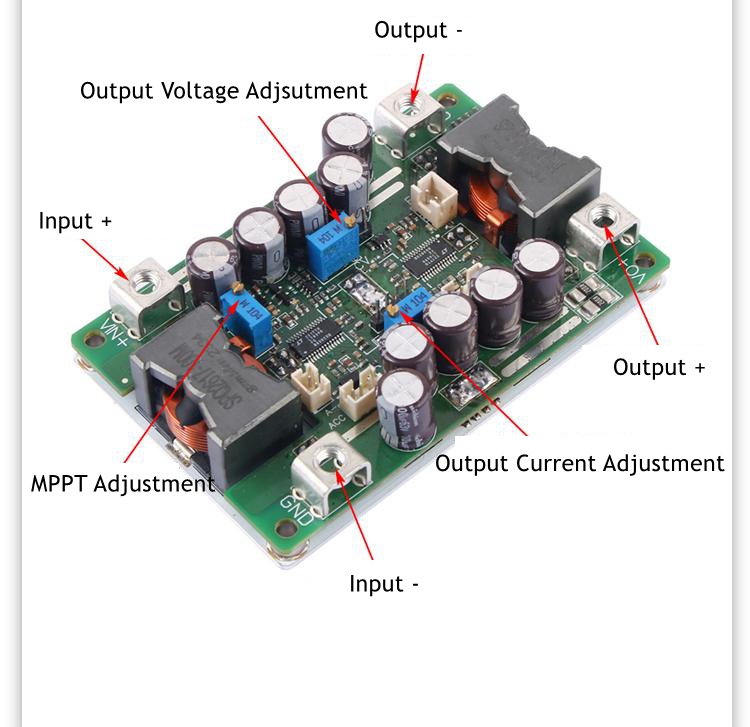
Interface Introduction:
- VIN+: Power input positive pole; NPUT+. Can not be connected to AC, no reverse connection allowed.
- GND: Power input/output negative pole; Public negative electrode.
- VO+: Power output negative pole; The output positive pole should not be connected to the positive and negative poles of the battery in reverse.
- RX1: Output voltage regulation, increasing clockwise; 25 turns of the potentiometer correspond to a change in output voltage of 2.4-56V, with potentiometer open circuit protection. After the open circuit, the output voltage remains at 28V.
- RX2: Output current regulation, increasing clockwise; 25 rotations of the potentiometer correspond to a change in output limiting current of 5-59A. The specific current limit value needs to be measured and adjusted in practice.
- RX3: Input tracking voltage adjustment, clockwise increase, default counterclockwise decrease; The input tracking voltage of 9.5-56V is suitable for constant current source input applications such as fuel cells and battery panels. For example, set the maximum power voltage of 18V, input it to 18V, and then adjust the cvN potentiometer until LED1 lights up, or measure the maximum output current while adjusting. Note: Forcing the input voltage below the set value may result in no output or low current.
- P1-1: Output current external control interface, RX2 needs to be clockwise to the end; The external input voltage of 0.26-1.25V controls the output current to vary from 6-59A, and the driving capacity of this signal needs to be greater than 1mA, which is proportional.
- P1-2: Power enable interface; After connecting to GND, the entire power supply is turned off, including the auxiliary power board. It is recommended to use this interface for external shutdown.
- P1-3: To control the signal GND; External control GND interface.
- P2: The optional 12V temperature controlled fan interface requires an optional auxiliary electrical board to function; The lower part is +, the upper part is -, it only rotates when the temperature is high, and the fan current is less than 0.3A. If the positive pole of the fan is connected to an external power source for temperature control, no auxiliary power board is required.
- P3: The optocoupler isolation ACC power on interface requires the removal of the optocoupler rear stage 0R resistor; Control the power on after external supply of 5-28V. A+is connected to the positive pole, and A - is connected to the negative pole. If the optocoupler controls the power on/off, it defaults to not turning on when powered on, and the priority of EN is higher.
- P4-1: Voltage and current display meter interface (optional function) 14 are: Vo+, 12v, out, GND; After configuration, it can display the output voltage and current, with a 4-digit integrated display meter. It can only be displayed normally with an auxiliary power supply board or external power supply.
- P5: The output voltage external control interface (left signal interface, right GND) RX1 should not be counterclockwise to the bottom, and it is recommended to center it; After connecting to the 0-2V analog voltage signal, the output voltage can be controlled to change from 56V to 0V, which is inversely proportional.
- P6: Optional auxiliary power board; The normal operation of the auxiliary power board requires an input voltage of 14 or above. Note that the fan and display meter can only function after selecting an auxiliary power board.
- LED1: Input voltage tracking indicator light; Non constant current input source application, RX3 counterclockwise to the bottom, the light does not light up; Otherwise, there may be no output or a decrease in output current.
- LED2: Work indicator light; If the power is turned on, the light will remain on.
Note:
1: Testing this power supply must ensure that the input source can provide sufficient current (>65A) to ensure that the power supply does not collapse or even be damaged, especially when starting on load.
2: The startup time of the input source must be less than the startup time of the local power supply (such as the adapter as input), otherwise it may not be able to start with load.
3: The input wire connected to this power supply must not be too long (the internal resistance of the wire must not be too high), otherwise the power supply may cause vibration and abnormalities.
4: If there is a diode connected in series from the input source to the power supply, the power supply may be damaged due to surge voltage caused by instantaneous connection and shutdown (BOOST effect of the line). Long wires should ensure that the input voltage is used below 50V, leaving enough margin.
5: Do not use the CC mode of electronic loads as the load of this power supply. It is recommended to use the CR mode. CC mode absorbs current, this power supply has current limit, and in a constant current state, it will cause the power supply to crash.
6: Suggest adjusting the output voltage to connect a small current resistor load (false load) to ensure real-time adjustment of the output voltage potentiometer, otherwise the output voltage changes slowly; The adjustment value is not accurate.
7: The current limiting value shall be set in resistance CR mode or battery with less than 60% charge. For example, first set the no-load voltage of 29.4V, then set the current limiting value of 20A, then the load resistance of 29.4 * 0.6/20A<R<29.4 * 0.8/20A is 0.88Ω~1.17Ω, and the 1Ω resistance can be selected, and then adjust the potentiometer until the output current is 20A.
Package Included:
- 1 x Power Module


")


