| Quantity | 3+ units | 10+ units | 30+ units | 50+ units | More |
|---|---|---|---|---|---|
| Price /Unit | $8.68 | $8.51 | $8.24 | $7.89 | Contact US |
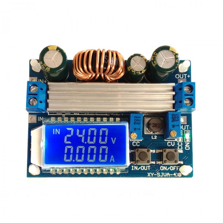
35W Adjustable Buck Boost Module Step Up Down Converter CV CC Voltage Current Meter with LCD Display
Features:
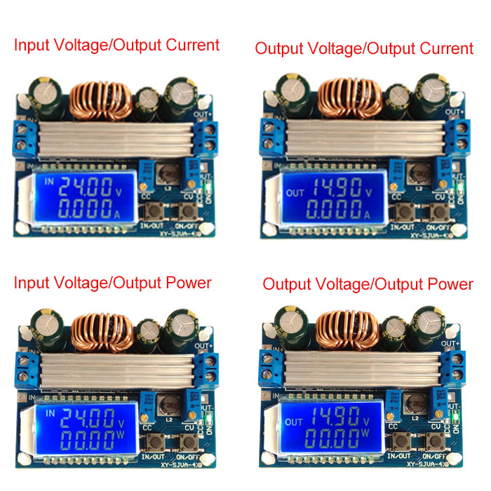
- LCD can display input and output voltage, output current and output power
- Input terminal with reverse connection protection
- Can step up and step down. Output voltage can be adjusted freely from 0.5-30V. Limit current 0-4A arbitrary adjustment
- Anti-backflow protection at the output end, no need to add anti-backflow diode when charging
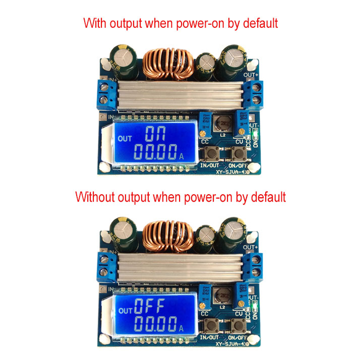
- Control the ON / OFF state of output terminal by buttons, and you can set the power-on default state to ON or OFF
- Step-up and step-down chip is used as the main controller, the external 60V 75A MOS tube is used as switching tube, and dual 60V 5A SS56 are used for rectification, over-shadowing XL6009 / LM257 solution
- Output ripple is small, with LC filtering
- With heat sink
Specifications:
- Input voltage: 5.5-30V (When input voltage is 5V, it can achieve normal buck-boost, but the voltage and current meter values are not accurate. When it is below 4.7V, under-voltage protection works)
- Output voltage: 0.5-30V
- Output current: stable operation in 3A for a long time; can reach to 4A with advanced heat dissipation condition
- Output power: 35W natural heat dissipation, advanced heat dissipation 50W
- Voltage display resolution: 0.05V
- Current display resolution: 0.005A
- Conversion efficiency: about 88%
- Soft start: Yes (High power load modules may fail when starting)
- Input reverse connection protection: yes
- Output end against flowing backward: yes
- Short-circuit protection: yes
- Working frequency: 180KHZ
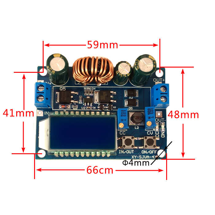
- Mounting hole: diameter 4mm
- Weight: 46g
Functions Instruction:
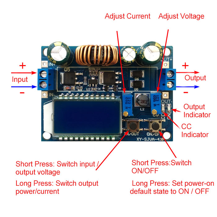
1.The module has two buttons IN / OUT, ON / OFF. IN / OUT button switches input voltage and output voltage display. Press and hold this button to switch output current and output power display.
ON / OFF button controls output ON or OFF. Press and hold this button to set default output state to ON or OFF when power-on again.
2.CC is current setting potentiometer. Turn it clockwise to increase set current. When load current reaches the set current, it enters constant current state, and CC indicator (red) lights up. CV on the right is a voltage setting potentiometer. Turn it clockwise, output voltage can be increased. ON indicator is an output status indicator. It is lit when there is voltage at the output end, otherwise it is off.
Using Method:
1.Used as a common buck-boost module with over-current protection capability
(1)Adjust CV potentiometer to make output voltage reach the voltage value you want.
(2)Use multimeter 10A current to measure output short-circuit current (just connect two test probes directly to output end), and adjust CC potentiometer to make output current reach predetermined over-current protection value. For example, current value displayed by a multimeter is 2A, then the maximum current when you use the module can only reach 2A. When current reaches 2A, red CV CC indicator is on, otherwise the indicator is off.
Attention: When used in this state, because output terminal has current sampling resistor, there will be a voltage drop of 0 ~ 0.2V when connected to load. At the same time, when the current is large, input and output wires will have a certain line voltage drop. It is normal.
2. Use as a battery charger
Modules without constant current cannot be used to charge battery. Due to large voltage difference between drained battery and charger, when charging current is too large, battery will be damaged. Therefore, at the beginning, battery should be charged with constant current. It will automatically switch back to constant voltage when charging reaches a certain level.
Note: Batteries are not included in the package.
(1)Determine floating charge voltage and charging current of the battery you need to charge. If lithium battery parameter is 3.7V / 2200mAh, then floating charge voltage is 4.2V, and the maximum charging current is 1C, which is 2200mA.
(2)Under no-load conditions, a multimeter measures output voltage and adjusts CV potentiometer to make the output voltage reach the floating charge voltage. If you charge a 3.7V lithium battery, adjust output voltage to 4.2V.
(3)Use multimeter 10A current to measure output short-circuit current (just connect two test probes directly to output terminal), and adjust CC potentiometer to make output current reach predetermined charging current value.
(4)Connect to battery to charge.
(Steps 1, 2, and 3 are: input end is connected to power supply, and output end is not connected to battery without load.)
3. Used as a high-power LED constant current driver module
(1) Determine working current and maximum working voltage you need to drive LED;
(2) Under no-load conditions, a multimeter measures output voltage and adjusts CV potentiometer so that output voltage reaches the maximum working voltage of LED;
(3) Measure output short-circuit current with multimeter 10A current, and adjust CC potentiometer to make output current reach predetermined LED working current;
(4) Connect LED and test.
(Steps 1, 2, and 3 are: the input is connected to power supply, and the output is not connected to LED light.)
Attention: When this module is used over 3A, 35W, please strengthen heat dissipation condition.
Precautions:
1.IN- of the module is forbidden to be short-circuited with OUT-, otherwise constant current function is invalid.
2.Make sure that the power of power supply is greater than the power required by output load.
3.If you want the module to output at full load, input voltage must be above 8V.
When input voltage is 5V, output power is about 15W, and the voltage ammeter fails. The maximum current value of the module is 4A, and the premise is limited by the maximum output power. For example, if output is 17V, current should not be greater than 2A.
4.Module with output short-circuit protection. After short circuit protection is turned on, the module automatically turns off output. Power on the module to recover. If your power supply does not have output current limit protection, it is recommended to connect a fuse in series with the front end of the module input to improve safety factor.
5.The module has an input under-voltage protection function. The default is about 4.7V. Below this value, output is automatically disconnected. Power on the module to recover (Please note that the voltage here is the voltage at the port of the module. When input current is relatively large, do not ignore the divided voltage on input wire).
6.Certain electronic knowledge is highly recommended. Please read the product description carefully before use. The product is not designed for medical, life saving, life support and other purposes, and cannot be used in hazardous places such as coal mine depots.
Package Included:
- 1 x Buck Boost Module