| Quantity | 3+ units | 10+ units | 30+ units | 50+ units | More |
|---|---|---|---|---|---|
| Price /Unit | $92.38 | $90.50 | $87.67 | $83.90 | Contact US |
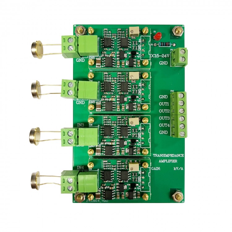
500kV/A 20uA 4-Channel IV Conversion Amplifier Module Photodiode Detector Transimpedance Amplifier Photoelectric Sensor
Description:
- IVZ4AMP1656SP is a 4-channel cross resistance amplifier with a gain coefficient range of 10k-500kV/A. It has a 1000KHZ signal bandwidth at a gain of 100kV/A, excellent noise performance within the bandwidth, and high bandwidth and amplification characteristics. The minimum current resolution of the transimpedance amplifier is 1nA, which is compatible and adaptable to the vast majority of high-speed and low current photodiode PD. The amplifier multi-channel design system has high integration, and the single power supply mode also simplifies power supply. Four channels are commonly used for displacement and direction detection in four quadrant photoelectric sensors. Paired with an analog-to-digital conversion collector, weak signal detection can be achieved, including pulse light conversion, laser ranging, high-speed photoelectric detection, and fluorescence substance detection.
Specification:
- Model: IV-4AMP1656SP
- Module type: transimpedance amplifier
- Power supply: DC15 - 24V
- Input signal form: single-ended current
- Input signal interface: 3.81-2PIN wiring terminal
- Input current range: 0 - 1000uA (according to the model you choose)
- Input current minimum resolution: 1nA (according to the model you choose)
- Gain ratio: 10k - 500k V/A (optional); accuracy ±10%
- Linearity: better than 1%
- Gain bandwidth: DC-500KHz at gain of 100k V/A
- Output impedance: low impedance
- Output voltage range: -3.3V to +12V (Hi-Z)
- Output Current: ±1mA (max)
- Bias voltage adjustment range: ±1V
- Module weight: 55g
- Module size: 60 x 90 x 15mm
- Module heating: without heat dissipation module, no need for heat dissipation for normal working
- Working temperature: -25℃ ~ +75℃
- Module features: high speed current to voltage, zero adjustable
- Application: photoelectric detector, data acquisition front-end, weak signal detection, etc.
- Module interface: 3.81-2PIN plug terminal, 3.81-2PIN wiring terminal, 3.81-6PIN wiring terminal
Precaution:
- The amplifier power supply is recommended to be a low ripple linear power supply to avoid excessive power noise affecting the measurement.
- Due to the fact that amplifiers are high-precision and high-speed devices, it is recommended to use high-quality short wire to avoid unnecessary interference.
- The input signal cannot exceed the range or be overvoltage input, and the module has no input protection circuit.
- Poor or low-quality input wires may cause signal attenuation or excessive noise.
Testing Methods:
- The IV-4AMP1656SP is powered by a 15V linear power supply and tested to verify amplifier functionality and performance through two methods. For weak current input uses a common source function signal generator DG4102, which inputs sine waves with frequencies of 1KHz and 1MHz, amplitudes of 0-1V, and series connected 100K resistors to obtain a 0-10uA sine wave current. The standard sine wave voltage signal is obtained through module cross resistance conversion.
- The second testing method: The laser emission module drives the white LED to emit AC and DC varying light intensities, and the 4-channel receiving end uses 2CU8300 low-speed photoelectric PIN to receive light signals and convert them into current signals. The 4-channel current signals are respectively converted into corresponding voltage signals in the cross resistance amplifier. Able to perceive the displacement and position of the object being tested. If a 4-quadrant photoelectric sensor is used, the effect will be even better.
FAQ:
Q: Connect the photoelectric tube, and after light irradiation, the output shows almost no response?
A: Firstly, it is necessary to confirm how much current is generated by the photocell under the current light intensity. A multimeter can be used to measure the current of the two pins of the photocell, and the output voltage can be calculated based on the photo-current. If the input current is too small, the output will have almost no response.
Q: Is there significant noise in the input current signal and output voltage?
A: Firstly, you should use our matching wire for wiring and measurement. The input wire should not be too long or unshielded, as this can easily introduce external noise. The input current line should be as short and shielded as possible.
Package Included:
- 1 x IV Conversion Amplifier Module

