| Quantity | 3+ units | 10+ units | 30+ units | 50+ units | More |
|---|---|---|---|---|---|
| Price /Unit | $52.23 | $51.17 | $49.57 | $47.44 | Contact US |
 RideNow R1 100PSI Mini Electric Air Pump Electric Bicycle Pump Bike Pump for 7.4V Fast Inflation
$60.02
 RideNow R1 S 120PSI Mini Electric Air Pump Bike Pump with Air Pressure Display + 7.4V for Inflation
$81.78
 RideNow R1 MAX 150PSI Mini Electric Air Pump with Preset Tire Pressure + Display + 11V Inflation
$83.72
6S 24V Electric Skateboard Controller Dual Motor Driven Type with Remote ESC Substitute
Description:
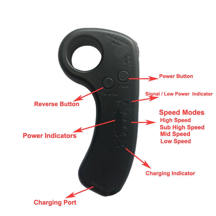
The electric longboard skateboard control system comes with a latest remote controller. This control module would be more stable and cheaper. It supports dual motors.
Features:
- A sine wave scheme makes it work more stable than the ESC and it is not easy to burn out
- Low speed but with high torque
- Two-way Communication: You can check the power of the skateboard through the remote control
- Multiple Protections: It features low-voltage alarm function, under-voltage and power-failure protections
- Max. Load Capacity: 120kg
- Fit Hub Motor RC Motors: 5055 5065 6354 6364 6374 6384
How to Connect the Remote Control and the Controller Board:
1. Connect the control board to power source.
2. Turn the control board power on, wait for 2 seconds. Then press and hold the switch for about 6 seconds till the power indication light flickers.
3. Turn on the remote control and use a small screwdriver to press the code synchronize switch in the lower left corner of the remote control.
4. Turn off the remote for two seconds and then turn it on. Wait for the remote control signal light and the switch signal light to flash at the same time, which means that the match is finished.
Specifications:
- Item Name: Four-wheel Skateboard Longboard Controller Set
- Rated Voltage: 24V 6S
- Sensing Mode: Hall
- Material: Plastic Shell
- Max Load Capacity: 120kg
- G.W.: 0.5kg
Package Included:
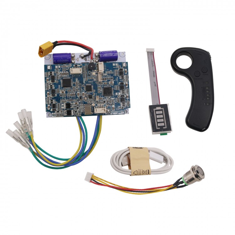
- 1 x Remote controller
- 1 x Control Panel
- 1 x Thermal Baffle
Note: Please not connect motor cables in parallel to make single driver to drive two motors.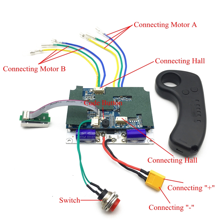
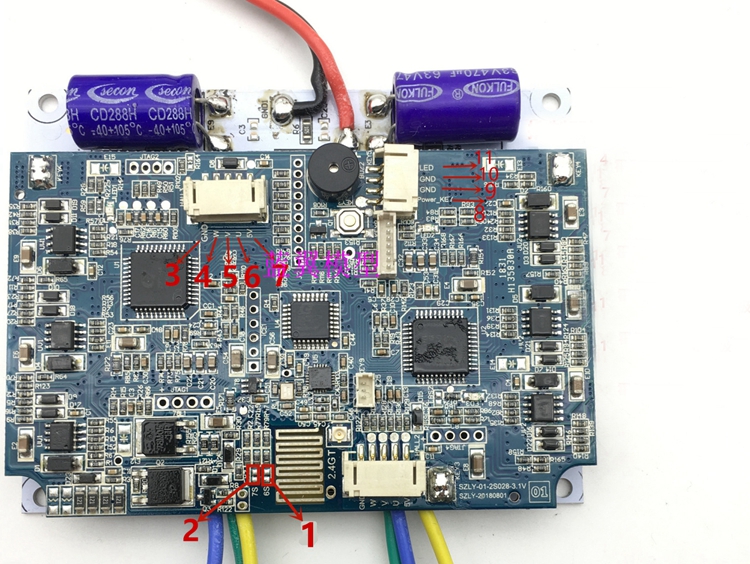
Instructions for Changing the Voltage of the Controller:
6S 24V: Connect Point 1, Disconnect Point 2
7S 29.4V: Connect Point 2, Disconnect Point 1
10S 36V: Disconnect Point 1, Disconnect Point 2
Hall Sensor Connection:
3: Black (-) – GND
4: Orange (C) – W
5: White (B) – V
6: Yellow (A) – U
7: Red (+) – 5V
8 & 9: Connect the Switch (No distinction between positive and negative)
10: Switch Indication Light GND (-)
11: Switch Indication Light +
