| Quantity | 3+ units | 10+ units | 30+ units | 50+ units | More |
|---|---|---|---|---|---|
| Price /Unit | $45.80 | $44.86 | $43.46 | $41.59 | Contact US |
 BN320 380-780nm Handheld LED Spectral Illuminometer CCT/Lux/Ra Testing with 4-inch HD LCD Touch Screen
$273.04
 Secondhand Imported UP19K-50L-H5 Laser Power Energy Meter 90W/15J Rang & Software Display for GENTEC
$538.14
 F999M Portable Professional Leakage Detector for Water Pipes/Heating Pipes/Fire Hoses Leakage Detection
$498.30
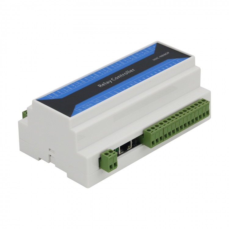
8 Channel IP Network Relay Controller RS485 To Ethernet Switch Quantity Controller With Shell
Features:
- This product is high temperature resistant and can work in an environment of -40℃ to 85℃.
- Strong anti-interference ability, can be connected to external high-current AC contactors and relays, and will not crash under strong electromagnetic interference.
- Real 100M speed can communicate reliably under the condition of sending commands with zero delay.
- Industrial grade products. Support automatic acquisition of IP.
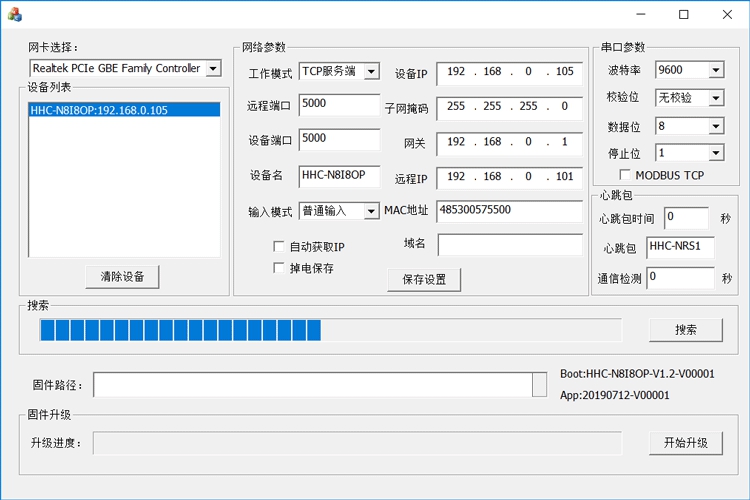
- Support 10pcs TCP client connections under TCP server. Through the provided configuration software, you can configure 5 working modes: TCP server, TCP client, UDP server, UDP client, DNS domain name.
- With an RS485 port, it supports transparent transmission from Ethernet to RS485.
- 8 relays, 8 switch inputs, with fully open and fully closed inputs.
- With power-down save function (save relay status).
Electrical Parameters:
- The power supply is DC 7-24V, and the DC socket or terminal block can be selected for input power. The DC connector specification is 5.5-2.1MM (outer diameter-inner diameter).
- The board operating temperature range is -40℃ to 85℃.
User Manual:
- 8 independent relay outputs, output without voltage. The DC rating of a single relay is 10A, the AC current rating is 10A, the maximum AC rating is 250V, and the maximum DC rating is 30V.
- 10-channel independent input. IN9 means fully open. After IN9 has a switch input, all relays are closed. IN10 means fully closed. When IN10 has an output, all relays are closed. The 8 inputs of IN1-IN8 can be configured into three different working modes through the configuration parameter tool, which can be selected in the "input mode" of the configuration tool. "Normal input" mode collects input signals normally. To obtain the input status, send a read input status command to the device. "Trigger relay" mode. After this mode has input, the corresponding relay state is reversed, and IN1-IN8 control corresponds to 1-8 relays. "Active upload" mode, this mode will actively send the input status to the network connected to the device when the input changes.
- The device has an RS485 interface. It can be controlled by RS485 equipment from other manufacturers. It can realize the transparent transmission of network data to RS485 data. The baud rate is configurable from 300 to 115200. When parity is used, the data bits must be configured to 9 bits, and the serial port parameters are configured through the configuration tool.
- The device has a power-down save function, which can save the state of the relay and can be configured through the configuration tool.
- Reset the configuration. The RESET position with the silk-screen label is the button for restoring factory settings.
Introduction of Working Mode:
The working mode is configured with the provided configuration software.
1. TCP server: In this mode, you can only connect to the device through a TCP client, and support 10 TCP client connections.
2. TCP client: In this mode, the device actively connects to the TCP server (the remote IP and remote port number are the parameters of the device connection). Only one server can be connected.
3. UDP server: In this mode, any UDP communication is supported.
4. UDP client: In this mode, only UDP communication conforming to the remote IP and remote port number (configuration software settings) is supported.
5. DNS domain name: In this mode, the device uses a TCP client to connect to the TCP server of the bound domain name (the port is the remote port).
High-speed Communication:
With high-speed communication, a computer no longer has to wait for data to be sent to the device, and any device can be processed. Working under the TCP server, the device supports 10 TCP clients to continuously send data. Network chips that are not SPI ports are comparable, such as ENC28J60, W5500 and other chips. The real 100M network port.
Command Explanation:
The above commands are sent and received in character form. There is no carriage return or space after the command. To send in hexadecimal system, check the ASCII code table to convert by yourself.
Get Device Name:
- Send: name
- Return: name="HHC-N8I8OP"
HHC-N8I8OP is the device name, which can be configured by the configuration tool.
Control 1st Relay:
- Send: on1
- Returns: on1
Turn Off 1st Relay:
- Send: off1
- Returns: off1
The command format is on and off followed by the relay channel, 2-8 channels are controlled as above.
Control All Relays:
- Send: all00000011
- Returns: relay00000011
All is to control all the relay commands, the following 8 channels are controlled, 1 means to pull in, 0 means to release. The above command means that the first and second channels are pulled in, and the 3rd to 8th channels are released. After this command is executed, the status of the relay is returned. The status return information of the relay is the same as the information returned by the read command.
Delay Control:
For example, if you want the relay to be closed for 2 seconds and then released, you can send the following command:
- Send: on1:02
- Returns: on1
The above command means that the relay will be released after being closed for 2 seconds, on1: represents the relay to be controlled, followed by the delay time, the maximum is 99 seconds, for example, on2:12 means that the second relay will be released after being closed for 12 seconds. The other 2-8 channel control is the same as above.
Read Relay Status:
- Send: read
- Return: relay00000001 (indicating the status of 8 relays, 1 means the relay is closed, 0 means if the relay is released, the above means the first relay is closed, 2-8 relays are released)
Read Switch Quantity:
- Send: input
- Returns: input00000001
Input is followed by 00000001, 1 means there is a switch input, 0 means there is no switch input, it means the input state of the 8-channel switch, the above instruction indicates that the first channel has a switch input, and the 2-8 channel has no switch input. The 9th and 10th switches are used to control the fully open and fully closed relays and cannot be read. The input is configured to "active upload" mode, when the switch input changes, the above return information will be automatically sent.
Configuration Screenshot:
Package Included
- 1 x Relay Controller
Note: It comes with a shell. Power supply is not included.