| Quantity | 3+ units | 10+ units | 30+ units | 50+ units | More |
|---|---|---|---|---|---|
| Price /Unit | $36.36 | $35.62 | $34.50 | $33.02 | Contact US |
 Secondhand Imported UP19K-50L-H5 Laser Power Energy Meter 90W/15J Rang & Software Display for GENTEC
$538.14
 F999E Portable Leakage Detector 4-Level Adjustable for Water Pipes/Heating Pipes/Fire Hoses Leakage Detection
$434.17
 F999L Portable Leakage Detector High Sensitivity Indoor Sensor for Water Pipes/Heating Pipes/Fire Hoses Leakage Detection
$266.56
800W 30A DC-DC Step Down Buck Converter High Power CV CC Adjustable MCU For Solar Power Charging
Main Parameters:
- Product name: high-power step-down module
- Input voltage: DC 20-70V
- Input current: 20A Max
- Output voltage: DC 2.5-58V
- Output current: 30A Max.
- Output power: 800W Max.
- Standby current: ≤70mA (input 24V, output 12V) corresponding to different voltages, the standby current is different.
- Output ripple: ≤120mV. Input 24V, output 12V/20A
- Conversion efficiency: 0.92-0.96
- Circuit structure: no isolation
- Working temperature: -20 to 50℃
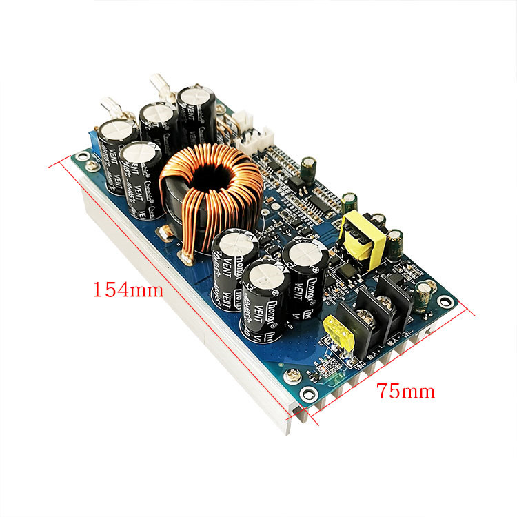
- Dimensions: 154*75*69mm
- Product net weight: 550g
Features:
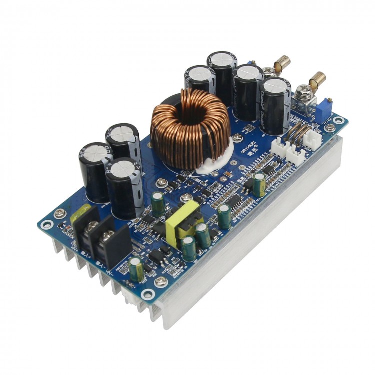
- This module uses high-performance original electronic components, the overall performance is more stable.
- Wide input and output voltage range, high output current and high power.
- Input low voltage protection (when the input voltage is lower than 20V, turn off the output).
- Output constant voltage and current, continuously adjustable voltage and current.
- There are output current test points, you can use a multimeter to test the value of the output current setting in the mV gear.
- There is an external voltage and current analog signal input terminal, which can be controlled by MCU to adjust voltage and current.
- There is an external output switch signal terminal.
- The input terminal Mos tube anti-reverse connection function, the product will not burn out when the input terminal is connected to the reverse polarity.
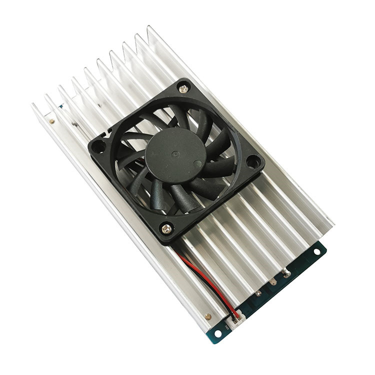
- Intelligent temperature control fan, when the temperature of the module rises, the fan starts about 55℃, and the temperature of the module decreases, and the fan shuts down about 50℃.
Applications:
- This module can be used to input high-voltage batteries and charge low-voltage batteries (Batteries are not included).
- Various occasions requiring high voltage drop to low voltage and high current.
- Solar step-down charging.
- DIY a step-down DC adjustable module, you can replace the original adjustable with an external adjustable (voltage 100K current 1K), easy to use. The external adjustable must be wound with good quality multi-turn wire. Poor quality will damage the module, and the external wiring should not exceed 15cm.
Package Included:
- 1 x Step Down Module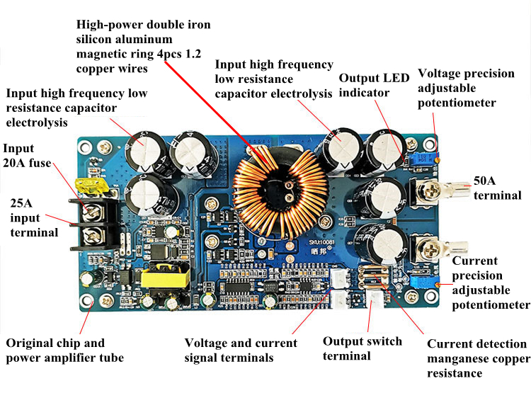
Instructions For Use:
1. Input and output cannot be reversely connected, and output positive and negative electrodes cannot be reversely connected or short-circuited.
2. The maximum input peak voltage cannot exceed 78V. Too high voltage may damage the module, please use the module within the voltage range.
3. The output voltage and current are continuously adjustable. Rotate counterclockwise to increase, clockwise to decrease, and the minimum adjusted current is 1A.
4. When the input voltage of this module is lower than 30V and the output is lower than 12V, the output can be short-circuited without damaging the module. You can use an ammeter to short-circuit the output modulated output current (but try to short-circuit at low voltage).
5. When adjusting output current, you can adjust the current while using the mV gear of a multimeter to measure the output current reference point voltage. Every 2mV is 1A of output current. Adjust the reference point voltage according to needed current.
6. Two diodes D 9 and D 10 can be changed to two LED light-emitting diodes, which can be used as constant voltage and constant current working status indicators (can only be changed on the original position of the board, not leaded by wires). Attention: Professional knowledge is highly recommended.
7. When the voltage and current are adjusted by external analog signals, the external voltage signal is 0-5V. Pay attention to the positive and negative poles when connecting. Note: When powering external signals, a separate power supply is required, and the ground wire cannot be shared with the module, otherwise the module may be damaged.
8. When you need to adjust the external analog signal, you need to remove two resistors, and when you need to adjust the voltage, remove R38 (the second resistor behind the voltage signal port). When you need to adjust the current, remove R46 (the second resistor behind the current signal port). At this time, the voltage and current can be adjusted to adjust the voltage and current respectively. If you don't need adjustable correction, you can change it to a corresponding fixed resistance.
9. This module is not suitable for loads with motors and large starting currents.
10. The maximum output power of this module is 800W. When the output voltage is below 26V, the maximum output current can reach 30A. When the output voltage is higher than 26V, the output current is reduced accordingly. This data is for reference only, and the actual use environment and conditions shall prevail.
11. The anti-reverse connection and current detection of the MOS tube of this module are at the negative (ground) end. When the output requires constant current and current limiting, the negative terminals of the input and output cannot be shared or short-circuited, and must be separated.
12. When using, please add heat sink to the module according to different environments and the size of your load.
13. Description of input and output voltage difference:
A: Input 70V, maximum output 58V.
B: Input 60V, maximum output 49V.
C: Input 50V, maximum output 40V.
D: Input 40V, maximum output 32V.
E: Input 30V, maximum output 24V.
F: Input 20V, maximum output 16V.
Attention: If you are not a professional, please not modify the module to avoid damage.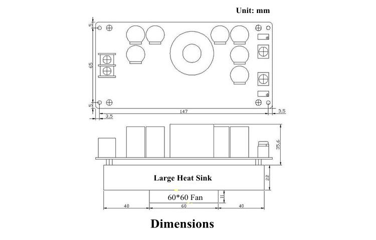
Precautions:
1. When input or output voltage exceeds 36V, please use it carefully and beware of electric shock.
2. When the temperature of this module reaches 65℃ or above, please add heat dissipation device in time.
3. Please pay attention to moisture and dust when using.