| Quantity | 3+ units | 10+ units | 30+ units | 50+ units | More |
|---|---|---|---|---|---|
| Price /Unit | $56.31 | $55.16 | $53.44 | $51.14 | Contact US |
 AD9379-A RF Evaluation Board Dual RF RX/TX Replacement for ADRV9009 Transceiver RF Board
$833.04
 USB/MIDI Dual-mode Computer Volume Adjuster Music Play Controller Compatible with Windows/Mac Systems
$81.65
 BU-5 Bluetooth Module Radio Bluetooth Adapter Unit for Yaesu FTM-150R FTM-510DR Transceiver
$55.79
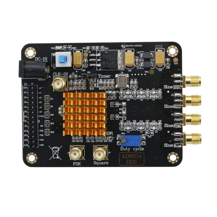
AD9854 Signal Generator Module High Speed DDS Module Signal Source Sine/Square Wave Signal Generator
Description:
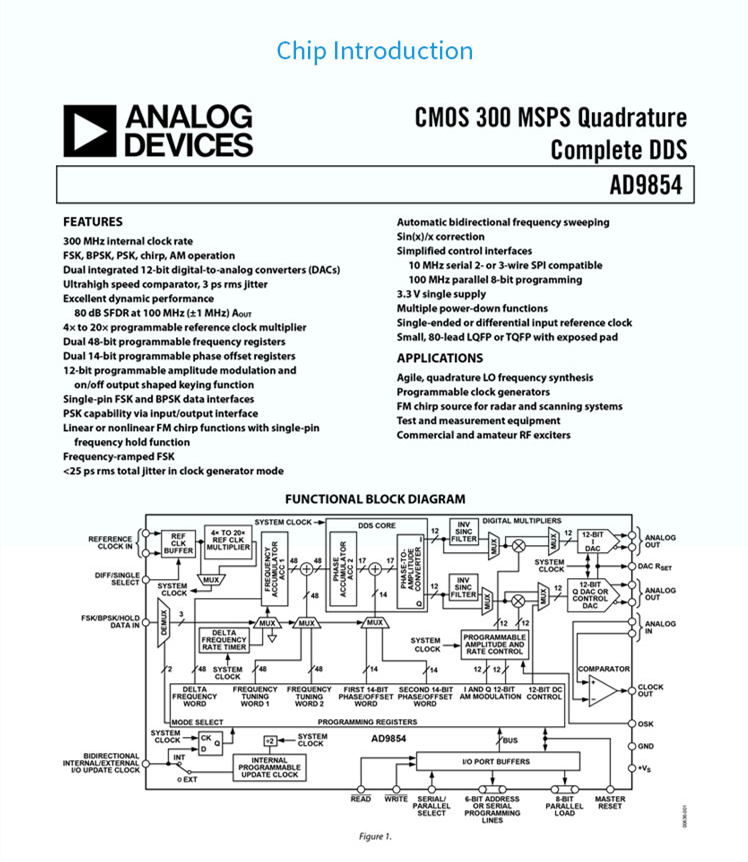
The AD9854 digital frequency synthesizer is a highly integrated device that uses advanced DDS technology and built-in two high-speed, high-performance quadrature DAC to form a digitally programmable 1 and Q frequency synthesizer. Using a precision clock source as a reference, the AD9854 can produce highly stable frequency phase, amplitude programmable sine and cosine outputs, and can be used as an agile L0 in communications, radar and many other applications. The innovative high-speed DDS core provides 48-bit frequency resolution (with 300 MHz SYSCLK, the tuning resolution is 1μHz) Maintaining 17 bits ensures that the device has excellent spurious-free dynamic range (SFDR).
Specification:
Model: AD9854
Type: digital synthesis frequency source
Power supply: DC7-9V
Current: 650mA (MAX); quiescent current 90mA (TYP) normal drive current 620mA (TYP)
Communication Protocol: SPI parallel
Main Control Chip: STM32F103RCT6
Routine Platform: STM32F103X-M3, KEIL5 version source code
System Main Frequency: 300MHz (MAX)
DAC Resolution Digits: 12
Phase Accumulator Digits: 48 bits
Output Interface: SMA; 24-hour salt spray anti-oxidation
Output Signals: sine wave, square wave; sine wave with 120MHz low-pass filter; square wave coupling output
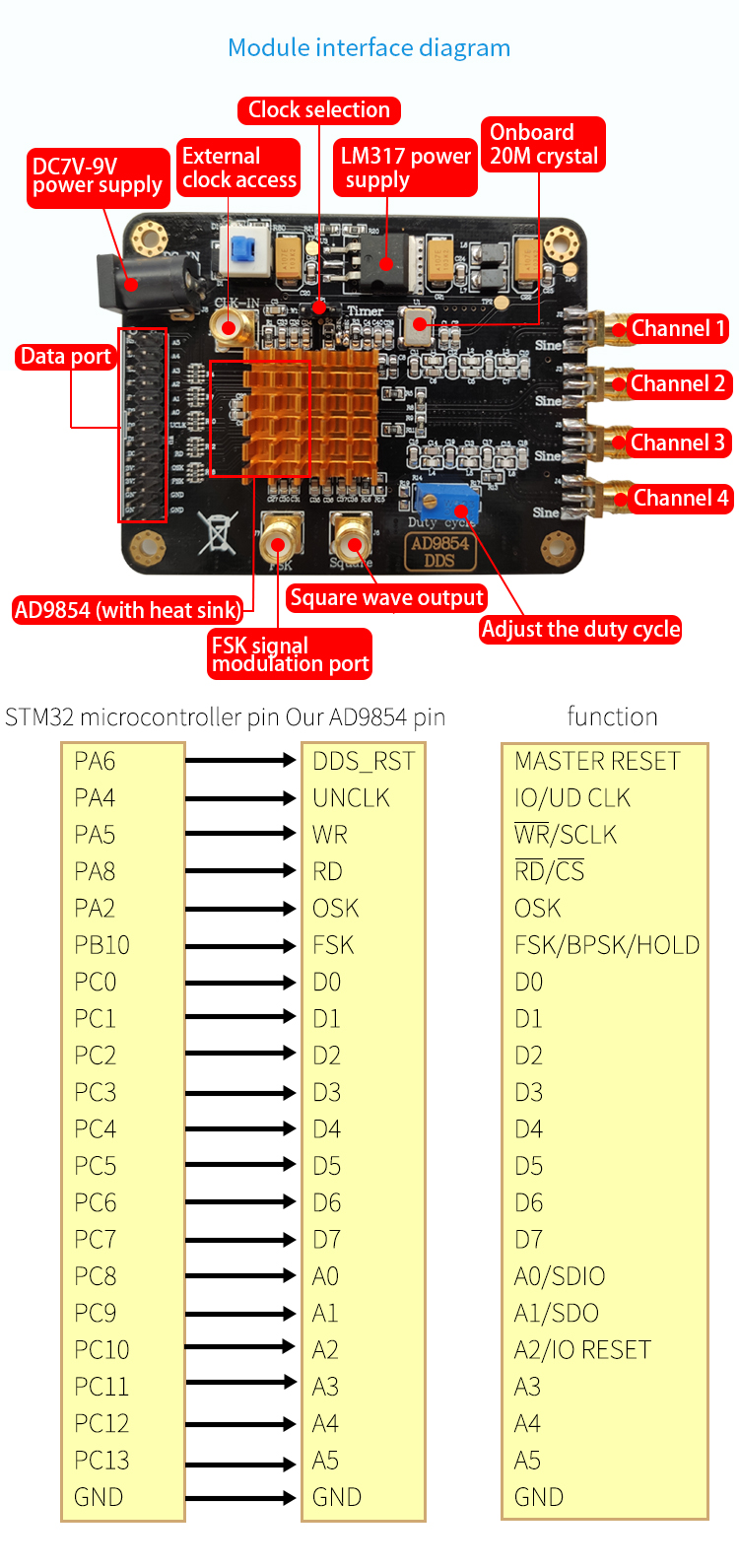
Output Channel: 5 channels; the phase difference between each pair is 90 degrees, the output of 1, 4 channels has filters, and 2, 3 channels have no filters. The square wave has a separate output.
Signal Characteristics: the sine wave square wave has no coupling output; the output has its own DC component. If it is connected to the radio frequency equipment, please add a DC blocker, or you can directly measure it with an oscilloscope. Square wave duty cycle adjustable range 5%-95%
Maximum Main Frequency Output Sine Wave Signal Range: 1Hz-120MHz
Maximum Square Frequency Output Square Wave Signal Range: 1Hz-50MHz; oscilloscope input impedance above 50MHz requires 50 ohms
Output Amplitude: sine wave 540mVpp (MAX) square wave 3.3Vpp; sine wave amplitude decreases with increasing frequency, square wave waveform changes with increasing frequency
Output Impedance: 50 ohms
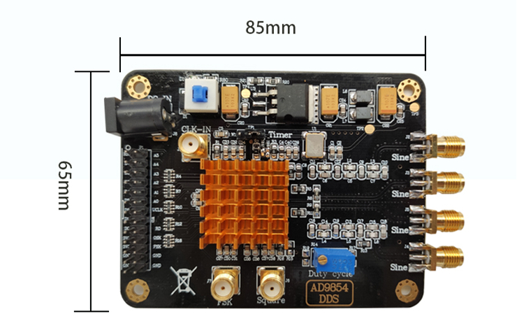
Size: 85*65*12; (length*width*height-PCB size)
interface type: SMA signal output and external clock input, DC5.5 power socket, XH2.54-26PIN double-row pin data interface
Features:
-Support external FSK signal input, high-performance DDS sine wave signal generator, high order elliptic filter, low-noise voltage regulator chip, etc.
-Applicable to frequency signal generation, sine wave, square wave signal generation, sensor excitation.
Package List:
1 x Signal Generator Module
Note:
(1) The current consumption of the module is large, and the power supply needs to have a certain margin. It is recommended to use a power supply above 7V1A.
(2) Since the module is a high-precision device, in order to avoid unnecessary interference, it is recommended to use a linear power supply.
(3) It is recommended to use the SMA to BNC cable to directly observe the output signal for the output signal. Poor contact or poor quality wires may cause signal attenuation or excessive noise.
(4) Due to the large power consumption and heat generation, pay attention to ventilation and heat dissipation for long-term work.
(5) If you need to simply test the function of the module, it is recommended to use it with the control board of our store. Power is supplied to the DDS module first, and then the power is supplied to the control board to generate a waveform. Long press the middle button to switch the function.
(6) The delivered code is only used for the supporting main control board, and does not provide a single-chip tutorial, additional functions need to be developed by themselves.
Q&A
Q: Can the main frequency and output amplitude of the module be adjusted?
A: The main frequency of the module is determined by the input clock and the program. The module can input the clock externally. The onboard default clock is 20MHz, and the program control frequency is 15 times, that is, the default frequency is 300MHz. The main frequency can be changed by modifying the input clock and frequency multiplier, and the output amplitude can be controlled by modifying the 12-bit amplitude register. You need to modify the program yourself.
Q: Can the module achieve frequency sweep? Can AM and FSK signals be generated?
A: The module can realize frequency sweep, the code provided by our store can support frequency sweep. The module can generate a simple AM signal, which needs to be programmed by itself; after generating the FSK signal, you need to configure the register, and then input the high and low levels from the FSK port of the module to generate the FSK signal
Q: Why is the waveform between channels not orthogonal when the frequency increases?
A: Due to the tolerance and delay effect of the filter, the higher frequency produces a different phase shift, so only when the frequency is lower is it strictly orthogonal.


