| Quantity | 3+ units | 10+ units | 30+ units | 50+ units | More |
|---|---|---|---|---|---|
| Price /Unit | $79.31 | $77.69 | $75.26 | $72.03 | Contact US |
 KSA5-mini Class A Headphone Amplifier Power Amplifier Small Headphone Amp (Main Unit + Power Adapter)
$115.76
 KSA5-mini Class A Headphone Amplifier Power Amplifier Headphone Amp with Small Volume (Main Unit)
$77.51
 TPA3255 High Performance Class D Power Amplifier Board 2.0 Channel Mini Digital Audio Stereo Amplifier Module
$26.56
B37 AK4137 DAC Board Decoder 384K DSD256 Support DSD PCM DOP + Remote Controller Kit Unassembled
Description:
This product uses advanced chip AK4137EQ as the core. The chip supports 32bit 786K, DSD256 input, asynchronous up-conversion, and can be set to output multiple different PCM and DSD formats. Using AK4118 as the coaxial signal receiver, it has the lowest Jitter in the industry. Through the comprehensive optimization of MCU soft control, the performance is much higher than that of WM8805, DIR9001, CS8416 and other programs.
Features:
1. Crystal oscillator independent power supply
2. Dual crystal oscillators. Use different crystal oscillator frequency according to output sampling
3. There are 5 inputs: BNC, RCA, optical fiber, AES, USB input (Suitable for our XMOS module/Italian USB)
4. BNC, RCA, optic, AES inputs support DOP DSD64
5. Support for XMOS module/Italian USB to be directly installed on the board, which can realize sampling display and support full frequency automatic switching
6. The dual-row 20-pin output interface is compatible with the output interface for Italian USB, and can be directly connected to decoder board such as DSC1
7. Can set 4 groups of filters
8. Adopt high-definition screen to display working status
9. All settings are automatically saved
Input:
- BNC RCA Optical, AES: 44.1K-192K 24BIT / DOP DSD64
- USB (For XMOS module): 44.1K-384K 32BIT / DSD64, DSD128, DSD256 (Module for XMOS or Italian USB is not included, please purchase separately)
Output:
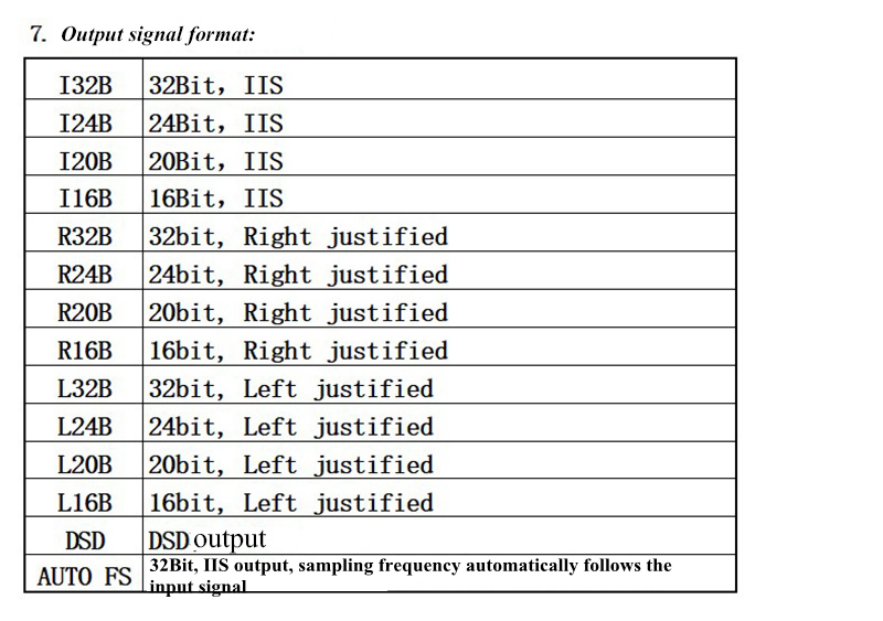
- Asynchronous output: PCM 44.1K ~ 384K / DSD64 / DSD128 / DSD256
(When DSD64 is converted to 44.1K / 48K, the output noise floor may be increased)
- Power supply voltage: regulated 5 volts, working current is about 100MA
Package Included:
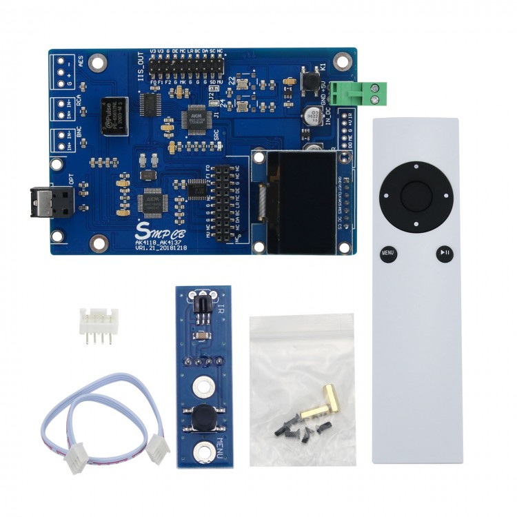
- 1 x AK4137 Board
- 1 x Remote Controller
- 1 x Switch Board with IR Receiver
- 1 x 2.54_4P Cable About 20cm
- 1 x 2.54_4P Pin Socket
Note:
- Soldering and assembling are needed.
- Hands-on ability and basic knowledge are highly recommended.
- Schematic diagram, component list and soft control code are not provided.
- Other items pictured are not included in the package. 
Function Description of J1 & J2 Jumper:
- J1 Connection: Signal for MCLK is provided by AK4137.
- J2 Connection: Signal for MCLK is directly provided by crystal oscillator.
Note: Only one of J1 and J2 can be connected. Both of them cannot be connected. 
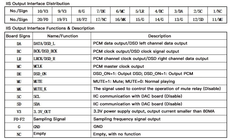
Output Sampling Indication (F0-F2 as follows, F3 is always 0):
Display and Functions:
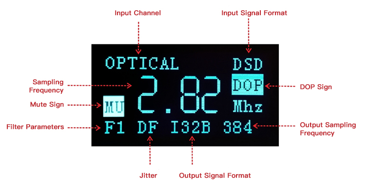
1. Input channel: COAX BNC, COAX RCA, USB, OPTICAL, AES/EBU
2. Input signal formats: PCM, DSD (Real-time display based on input signal)
3. Sampling frequency of the input signal(Real-time display based on input signal) 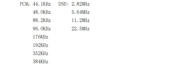
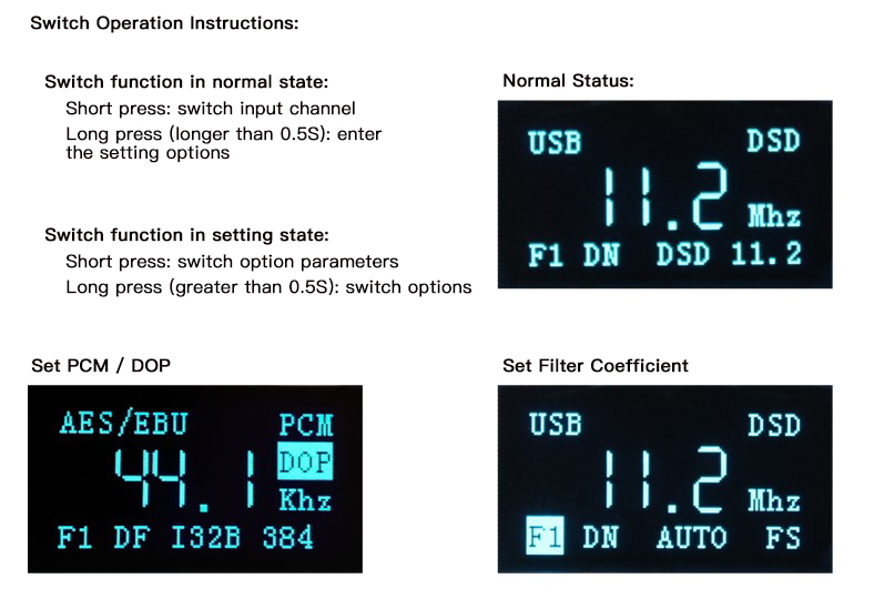
4.MU (Mute) Sign: When the remote control presses the mute button, the mute sign is displayed, and the board output signal is mute. The mute sign is not displayed during normal playing.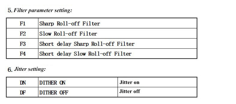

9.DOP Sign/DOP Switch (Settable):
- PCM: When DOP function is off, the normal PCM mode does not support DOP.
- DOP: When the DOP function is turned on, it supports DOP DSD64 signal adjustment to DSD64 output.
Attention:
1. This function is limited to COAX, BNC, COAX RCA, OPTICAL, AES / EBU input.
2. Due to hardware limitations, the DOP signal cannot be automatically recognized, and the DOP function needs to be manually turned on or off.