| Quantity | 3+ units | 10+ units | 30+ units | 50+ units | More |
|---|---|---|---|---|---|
| Price /Unit | $112.41 | $110.11 | $106.67 | $102.08 | Contact US |
 BU-5 Bluetooth Module Radio Bluetooth Adapter Unit for Yaesu FTM-150R FTM-510DR Transceiver
$55.79
BU-5 Bluetooth Module Radio Bluetooth Adapter Unit for Yaesu FTM-150R FTM-510DR Transceiver
$55.79
 STF10M1000M-25 RF Power Amplifier 10-1000MHz 25W-30W Wideband RF Amplifier without Radiator and Cooling Fan
$490.69
STF10M1000M-25 RF Power Amplifier 10-1000MHz 25W-30W Wideband RF Amplifier without Radiator and Cooling Fan
$490.69
 STF10M1000M-25 RF Power Amplifier 10-1000MHz 25W-30W Wideband RF Amplifier with Radiator and Cooling Fan
$543.48
STF10M1000M-25 RF Power Amplifier 10-1000MHz 25W-30W Wideband RF Amplifier with Radiator and Cooling Fan
$543.48
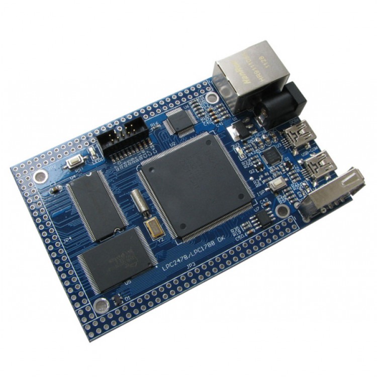
Cortex-M3 LPC1788 Development board for USB Host/Device SDRAM NORFlash
Items include:
- 1 X LPC1788 Development Board
- 1 X Ethernet Cable
- 1 X mini USB cable
Specification
- Model Number: LPC1788
- Processor: NXP's Cortex-M3 microcontroller in 208pin LQFP package
- on-chip flash 512 KB
- on-chip SRAM: 96 KB
- Power: +5V powering
- Debug Connector: 10 pin 2.0mm JTAG Port
- Dimensions: 99 x 64 mm
Features and benefits
- ARM Cortex-M3 processor, running at frequencies of up to 120 MHz..
- 512 kB on-chip flash program memory with In-System Programming (ISP) and In-Application Programming (IAP) capabilities. Flash program memory is on the ARM local bus for high performance CPU access.
- 96 kB on-chip SRAM includes::
- 64 kB of SRAM on the CPU with local code/data bus for high-performance CPU access.
- Two 16 kB SRAM blocks with separate access paths for higher throughput. These SRAM blocks may be used for DMA memory as well as for general purpose
- instruction and data storage..
- 4032 byte on-chip EEPROM
- LCD controller, supporting both Super-Twisted Nematic (STN) and Thin-Film Transistors (TFT) displays.
- Dedicated DMA controller.
- Selectable display resolution (up to 1024x768 pixels).
- Supports up to 24-bit true-color mode.
- External Memory Controller (EMC) provides support for asynchronous static memory devices such as RAM, ROM and flash, as well as dynamic memories such as single data rate SDRAM.
.- Eight channel General Purpose DMA controller (GPDMA) on the AHB multilayer matrix that can be used with the SSP, I2S, UART, CRC engine, Analog-to-Digital and
- Digital-to-Analog converter peripherals, timer match signals, GPIO, and for memory-to-memory transfers.
Serial Interfaces:
- Ethernet MAC with MII/RMII interface and associated DMA controller. These functions reside on an independent AHB.
- USB 2.0 full-speed dual port device/host/OTG controller with on-chip PHY and associated DMA controller.
- Five UARTs with fractional baud rate generation, internal FIFO, DMA support, and
- RS-485/EIA-485 support. One UART (UART1) has full modem control I/O, and one
- UART (USART4) supports IrDA, synchronous mode, and a smart card mode conforming to ISO7816-3..
CAN controller with two channels.
- Two SSP controllers, with FIFO and multi-protocol capabilities. One is an alternate for the SPI port, sharing its interrupt. SSPs can be used with the GPDMA controller.
- Three I2C-bus interfaces (one with open-drain and two with standard port pins).
- I2S (Inter-IC Sound) interface for digital audio input or output. It can be used with the GPDMA.
Other peripherals:
- SD/MMC memory card interface.
- Up to 165 General Purpose I/O (GPIO) pins depending on the packaging.
- 12-bit ADC with input multiplexing among 8 pins.12-bit ADC can be used with the GPDMA controller.
- 10-bit Digital-to-Analog Converter (DAC) with dedicated conversion timer and DMA support.
- Four general purpose timers/counters with 8 collection inputs and 10 compare outputs. Each timer block has an external count input.
- Two standard PWM/timer blocks with support for three-phase motor control. Each PWM has an external count input.
- RTC with separate power domain. Clock source can be the RTC oscillator or the APB clock.
- The RTC block includes 20 bytes of battery-powered
- backup registers, allowing system status to be stored when the rest of the chip is powered off.
- Windowed Watchdog Timer (WWDT). Windowed operation, dedicated internal oscillator, watchdog warning interrupt, and safety features.
- Single 3.3 V power supply (2.4 V to 3.6 V). Temperature range of -40 °C to 85 °C.
- 12 MHz Internal RC oscillator (IRC) trimmed to 1% accuracy that can optionally be used as a system clock..
- Four reduced power modes: sleep, Deep-sleep,power-down and deep power-down.
- Four external interrupt inputs configurable as edge/level sensitive. All pins on port 0 and port 2 can be used as edge sensitive interrupt sources.
- Processor wake-up from Power-down mode via any interrupt able to operate during Power-down mode (includes external interrupts, RTC interrupt, USB activity, Ethernet wake-up interrupt, CAN bus activity, port 0/2 pin interrupt).
- Two independent power domains allow fine tuning of power consumption based on needed features.
- Each peripheral has its own clock divider for further power saving. These dividers help reduce active power by 20 % to 30 %.
- Brownout detect with separate thresholds for interrupt and forced reset.
- On-chip power-on reset.
- On-chip crystal oscillator with an operating range of 1 MHz to 25 MHz.
- On-chip PLL allows CPU operation up to the maximum CPU rate without the need for a high frequency crystal. May be run from the main oscillator, the internal RC oscillator, or the RTC oscillator.
- Boundary scan for simplified board testing.
- Versatile pin function selections allow many possibilities for using on-chip peripheral functions.
- Standard JTAG test/debug interface as well as Serial Wire Debug and Serial WireTrace Port options.
- Emulation trace module supports real-time trace.
Applications
- Communications
- Industrial/Medical
- Consumer/Appliance
- Automotive
- Hardware
- 10/100 Ethernet Port
- 10 PIN 2.0mm JTAG Port
- USB 2.0 Full Speed
- USB Host
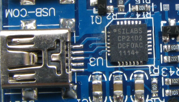
- USB-232 Port (using CP2102,can download programs by Flash Magic)
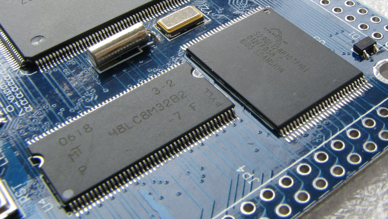
- 256 Mbit SDRAM
- 128 Mbit Flash
- SD Card Interface
- 1 push-button
- 1 LEDs
- Dimensions:99x64mm
Code
Network Routine
|
HTTP Web Server example |
It allows you to control the LEDs, read the AD value onboard through the webpage. |
|
LEDSwitch |
You can control the Hardware resources onboard from your PC by the way of UDP or TCP. PC program provide VC++ Code. |
|
LEDClient |
This program is a TCP/UDP Client example. It is used to send commands to a LEDSwitch Server connected on the same LAN. |
|
TFTP Server example |
It allows you to upload and download files from the board. |
|
Telnet Server example |
It allows you to control the equipment onboard by telnet Clients testing. |
|
SMTP Client example |
It shows you how to send a dynamic email to an email address. |
|
DNS resolve |
This program shows you how to resolve an IP address of a Host from the Host name. |
|
USB mass storage procedures |
Use on-chip RAM space as storage area. |
|
USB HID device program |
The board LEDs and Push Buttons can be accessed from the PC through a custom HID Client Program. |
|
SD_FILE program |
You can create, read, copy, delete files from the SD/MMC Flash Memory Card and format the card. |