| Quantity | 3+ units | 10+ units | 30+ units | 50+ units | More |
|---|---|---|---|---|---|
| Price /Unit | $108.48 | $106.26 | $102.94 | $98.51 | Contact US |
 DC Automatic Buck-Boost Power Supply Module 50A/65V with Heat Dissipation Sheet + Display Module + Cooling Fan
$112.05
DC Automatic Buck-Boost Power Supply Module 50A/65V with Heat Dissipation Sheet + Display Module + Cooling Fan
$112.05
 DC Automatic Buck-Boost Power Supply Module with Heat Dissipation Sheet 50A/65V Adjustable Constant Voltage and Current
$106.41
DC Automatic Buck-Boost Power Supply Module with Heat Dissipation Sheet 50A/65V Adjustable Constant Voltage and Current
$106.41
 DC Automatic Buck-Boost Power Supply Module Fast Response 50A/65V Adjustable Constant Voltage and Current
$104.86
DC Automatic Buck-Boost Power Supply Module Fast Response 50A/65V Adjustable Constant Voltage and Current
$104.86
DC Automatic Buck-Boost Power Supply Module with Heat Dissipation Sheet and Display Module 50A/65V
Precaution:
- The default intermittent mode allows for battery charging and has backflow protection. For applications with high dynamic requirements or energy recovery, continuous mode can be selected. To further improve reliability, it is recommended to add an ideal diode to the output.
- Hot plugging is prohibited (using wires to ignite and power on, air switches, relays, contactors, electronic switches are all considered hot plugging). If VIN is directly powered on, the original voltage of around 60V will produce oscillation spikes close to 100V. If the input wire has high inductance, the spike voltage may be even higher, exceeding the absolute maximum value and directly causing DC damage. If following the 50ms slow start process of the input switch power supply, it will be very smooth. Similarly, output short circuits can also cause DC damage due to inductive voltage spikes or even negative voltages in the circuit. If the short circuit characteristics are soft (high impedance), the pulse current will be low and relatively reliable. Frequent short circuits are not recommended.
Typical Performance (YF-BKT65V50A):
- Non-isolated four-switch synchronization buck-boost
- Wide input DC9 - 65V, output DC5 - 65V
- Peak efficiency: ≥98%, fast transient response
- Protection: overcurrent regulation, short circuit protection self-recovery, over temperature protection self-recovery
- Remote ON/OFF, temperature controlled fan
- Optional output voltage and current display
- Adjustable input voltage
- Adjustable output voltage and current
- External controllable output voltage and current
- The input voltage tracking function is suitable for battery board applications
- Battery charging backflow protection up to 70V, suitable for laser pumping with no overshoot current during startup.
- High voltage stabilization accuracy and constant frequency operation MEI facilitate prediction
- Power can reach over 2000W (input/output >48V)
- Unless otherwise specified, all tests were conducted at 48V input voltage, intermittent mode, pure resistive load, and 25 ℃ room temperature.
Absolute Maximum Rating:
- Input voltage: -1 ~ 70V (constant)
- Output voltage: -1 ~ 70V
- Power off interface (EN): -0.7 ~ 20V
- External voltage control interface: 0 - 5V
- External current control interface: 0 - 5A
- Fan interface current limit: 0.5A
- Storage temperature: -40 ~ 125℃
- Aluminum substrate and power pin withstand voltage: 300 - 500V (non-isolated)
- Maximum torque of screw terminal: 1 - 2N.m
- Potentiometer rotation life: 200 times
Recommended Using Parameter:
- Input voltage: 12.0 - 60.0V
- Input current: 40 - 50A
- Output voltage: 12 - 60V
- Output current: 40 - 50A
Input Characteristics:
- Input working voltage range: 9.0 - 65.0V
- Input tracking voltage adjustment range: 10 - 57.0V
- Input under-voltage protection adjustment range: 5 - 50.0V
- Undervoltage protection hysteresis value: 0.96*Vu - 1.04*Vu (Vu: setting undervoltage value)
- Input current operating range: 50 - 60.0A
- Input current limit value: 65.0 - 68.0A (do not use over current)
- No load input current value: 60.0 - 130.0mA (typ. 80.0mA)
- Shutdown current (complete machine shutdown): 0.5 - 1.0mA (0.7mA)
- Input reverse protection: not supported
- Hot swappable voltage: not supported, it can not be hot plugged for VIN>48V
Output Characteristics:
- Output voltage range: 5.0 - 65.0V
- Output current working range: 0 - 55.0A (typ. 50.0A)
- Output current adjustment range: 1.5 - 55A (note: it can be started at 0A)
- Output current limit: 57.0 - 58.0 A
- Short-circuit current (continuous): 57 - 58A (following current limit value)
- Output voltage regulation: -0.05 ~ -0.6% (typ. -0.3%) (Constant voltage with load drop/Vout)
- Output voltage ripple noise (PK-PK): 80 - 100mV (typ. 90mV) (56V to 28V/1500W)
- Output voltage ripple noise (PK-PK): 180 - 220mV (typ. 200mV) (28V to 56V/1300W)
- Output terminal absorbing current (power off): 0.02 - 1.0mA (typ. 0.4mA) (impedance 60Kohms - 500Kohms)
- Output reverse connection protection: not supported (do not connect the battery in reverse)
Dynamic Characteristics:
- Load step 56V to 28V/1500W: 1.6 - 2.0V (typ. 1.8V), (0% - 100% Iout)
- Recovery time: 0.5 - 0.8ms (typ. 0.7ms), (<2% Vout)
- Output voltage overshoot: 1.0 - 1.5V (typ. 1.2V), (load 100% - 0%)
- Recovery time: 0.8 - 1.2ms (typ. 1.0ms), (<2% Vout)
- Load step 28V to 56V/1350W: 5.0 - 5.8V (typ. 5.4V), (0% - 100% Iout)
- Recovery time: 0.5 - 1.0ms (typ. 0.7ms), (<2% Vout)
- Output voltage overshoot: 0.7 - 1.0V (typ. 0.8V), (load 100% - 0%)
- Recovery time: 0.5 - 1.0ms (typ. 0.7ms), (<2% Vout)
- Default intermittent mode: the maximum value of continuous mode decline and overshoot can be as low as half
- Start time: 380 - 400.0ms (power on to establish output voltage)
- Establishment time of output voltage: 360 - 380ms
Conversion Efficiency:
- 28V to 56V (1350W): 97.0 - 97.6% (typ. 97.4%)
- 56V to 56V (2300W): 97.8 - 98.22% (typ. 98.0%)
- 56V to 28V (1500W): 96.2 - 96.6% (typ. 96.4%)
Other Characteristics:
- Switch frequency: 220 - 260kHz (typ. 240kHz)
- Boost voltage differential ratio: 2 - 3 times (Vo/Vin)
- 50% reduction in differential voltage ratio (Iin): 3 - 5 times (typ. 4X), (Vo/Vin)
- Buck voltage differential ratio: 2 - 10 times (Vin/Vo)
- EN enables the effective voltage to be turned off: 0 - 1.1V (typ. 1.0V), (EN shutdown value shutdown output)
- Vo external control effective voltage: 0 - 2.0V (factory settings required)
- Voltage control signal load capacity: 5 - 10mA
- Iout external control effective voltage: 0 - 2.0V (factory settings required)
- Load capacity of current control signal: 1 - 10mA (typ. 5mA)
- Fan terminal power supply voltage: 11.0 - 12.0V (typ. 11.5V), (VIN >13V)
- Fan terminal power supply current: 0.3 - 0.5A
- Temperature controlled fan start value: 50℃ ~ 55℃
- Over temperature protection value: 85℃ ~ 90℃
- Power supply operating temperature: -40℃ ~ 80℃ (typ. 25℃)
- Storage temperature: -40℃ ~ 85℃ (typ. 25℃)
- Storage humidity: 5 - 95%RH (non-condensing)
- Cooling method: natural heat dissipation with a loss of less than 10W, and heat dissipation or air cooling with a loss of over 15W. (25℃ environmental temperature)
- Size: 100 x 65 x 20mm
- Net weight: 200g
Note:
1. Input voltage tracking is suitable for non constant voltage inputs such as battery panels, wind turbines, and wireless energy transmission receivers.
2: Input current regulation is suitable for adapters, switch power supplies, and other applications that require allocation or limitation of maximum input current.
3: The ripple current of the boost output capacitor is large, and the ripple current of the buck input capacitor is large. If there is a ripple requirement, you can add LC filtering.
4: It can be directly charged by connecting to the battery. It is recommended to adjust the output voltage correctly before connecting to the target battery. If high reliability is required, an ideal diode can be added to the output.
5: The situation where the startup time needs to be adjusted is when the input source startup time is relatively long. For example, if the AC adaptation output full load voltage establishment time is 50ms, and the startup time of this power supply is 15ms, it may cause the AC to fail to start normally.
6: For applications with frequent power outages, it is recommended to connect a current limiting resistor in series after turning off the EN, short-circuit the resistor, and then turn on the EN. Do not use high voltage to frequently hot plug and power on. It is not recommended to add a hard switch to VIN+.
7: Some parameters may be adjusted for different applications.

Interface Functions:
- VIN+: positive pole of power input: INPUT+; can not be connected to AC and in reverse.
- GND: power input/output negative pole; common negative.
- VO+: positive pole of power output; do not connect the positive and negative poles of the battery in reverse.
- RX1: output voltage regulation, increasing clockwise; 25 turns of potentiometer correspond to output voltage variation of 5-65V.
- RX2: output current regulation, increasing clockwise; rotating the potentiometer 25 times corresponds to a variation in output current limit of 0-55A. The specific current limit value needs to be obtained through actual measurement.
- RX3: input tracking voltage value adjustment (initially counterclockwise to the end), the principle is to reduce the output current value when the input source power is insufficient and the voltage is lower than the set value; Rotating the potentiometer 25 times corresponds to a change in the input tracking voltage value of 9-57V. For example, if the maximum power voltage of the solar panel is 36V, the output is connected to the load, and RX2 is adjusted clockwise until the output current is maximum, or if the input voltage is pulled down to around 36V, the current optimal state of the solar panel is adjusted.
- P1: temperature controlled fan power supply interface; Up for - and down for +, can be connected to a 12V fan, recommended current ≤0.3A.
- P2: optional voltage and current display interface; optional function, can display output voltage and current on a digital tube, and can also output current signals for sampling by a microcontroller.
- P2-1: negative interface; negative pole of current signal.
- P2-2: current sampling interface; sampling value V=0.025*Iout, for example, output current 10A, signal value is 0.25V.
- P2-3: auxiliary power supply 12V interface; power the display meter or provide external power of 12V/0.5A, with VIN>13V, otherwise the voltage will be unstable.
- P2-4: VO+ voltage interface; directly output VO+ voltage value, for sampling only, no current flow allowed.
- P3-1: control signal GND; to connect the negative pole of external control signal.
- P3-2: power supply EN enable interface; after pulling down to GND, turn off the output and completely disconnect the input and output. After external connection, try to stay away from the interference source and the undervoltage protection point as much as possible.
- P3-3: output voltage control interface (factory settings required); external analog voltage 0-2V can control output voltage 5-65V variation.
- P3-4: output current control interface (factory setting required); the external analog voltage of 0-2V can control the output current to vary between 1.5-55A. The current cannot range from 0A to 1.3A. Minimum recommended value ≥1.5A.
- LED1: standby indicator; when the power is turned on and the light is on, if it is not on, the input voltage is too low and it is not working or the power supply is completely damaged.
- LED2: error indicator; if the output voltage is normal, the light will turn on, but light off for the output overcurrent, short circuit, or over temperature protection situation.
- LED3: input voltage tracking indicator; when the input voltage reaches the maximum power point voltage, the light will turn on.
Note:
1: When testing this power supply, it is necessary to ensure that the input source can provide sufficient current (> 60A) to prevent the power supply from collapsing or even being damaged. Do not carry heavy loads or test complete functionality if it cannot be guaranteed.
2: The startup time of the input source must be less than the startup time of this power supply (such as using an adapter as input), otherwise it may not be able to start with load.
3: The input wire connected to this power supply must not be too long (the internal resistance of the wire must not be too high), otherwise the power supply may produce oscillations and abnormalities. Overvoltage damage to equipment or power supply caused by long wire pulse working current should be avoided.
4: If there is a diode connected in series between the input source and the power supply, there should be sufficient input voltage margin to ensure that the power supply is not damaged by overvoltage caused by instantaneous on-off.
5: Do not use the CC mode of electronic loads as the load of this power supply (it must be ensured that the input power is greater than the output power under any circumstances), it is recommended to use the CR mode. CC mode absorbs current, this power supply is limited in current, and constant current state will cause the power supply to collapse.
6: It is recommended to adjust the output voltage by connecting a small current resistor load (dummy load) to ensure the real-time adjustment of the output voltage potentiometer. Otherwise, the output voltage will change slowly and the adjustment value will be inaccurate.
7: It is not allowed to directly use the rectified AC voltage regulator as input. DC is equivalent to connecting to the power grid and is easily damaged. The small signal interface is also live and prone to electric shock. If it needs to be used, an isolation transformer must be added.
8: If the input voltage tracking value does not match the current input voltage, there will be no output. For example, if the input voltage is set to 48V and there is only 40V input at this time, there will be no output.
9: Four screws must be installed and fixed before connecting the copper nose to avoid excessive stress on the board and damage to the mechanical structure of the power supply.
10: The ESR of the solid-state capacitor output is very low, and if there is no output from the power supply, the battery cannot be directly ignited and connected. Connect after the voltage is established, or follow the EN enable.
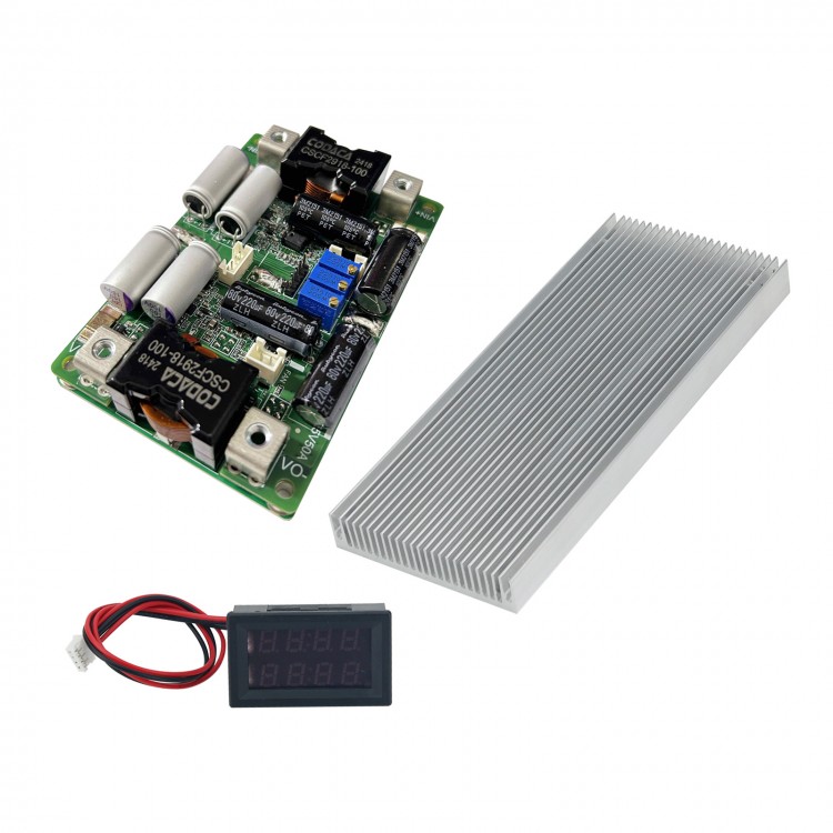
Package Included:
- 1 x Power Supply Module
- 1 x Heat Dissipation Sheet
- 1 x Display Module