| Quantity | 3+ units | 10+ units | 30+ units | 50+ units | More |
|---|---|---|---|---|---|
| Price /Unit | $127.28 | $124.68 | $120.79 | $115.59 | Contact US |
 EA15A-2 AVR Multifunctional Automatic Voltage Regulator Board for Brushless Diesel Generator
$72.31
EA15A-2 AVR Multifunctional Automatic Voltage Regulator Board for Brushless Diesel Generator
$72.31
 LMX2572 Core Board Phase Locked Loop 75mA 12.5MHz-6.4GHz Low Power Consumption PLL Module
$82.14
LMX2572 Core Board Phase Locked Loop 75mA 12.5MHz-6.4GHz Low Power Consumption PLL Module
$82.14
 XN-M0908C AC100-264V 1500W PFC Module without Guide Rail High Power AC-DC DPF Non-isolated Power Supply
$94.41
XN-M0908C AC100-264V 1500W PFC Module without Guide Rail High Power AC-DC DPF Non-isolated Power Supply
$94.41
High Voltage DC Buck Converter FPV Power Supply Board+Heat Dissipation Sheet+Cooling Fan+Display Module Kit 180V 12-54V/30A
Precaution:
- The output can be connected to the battery for charging, with an added ideal diode and backflow protection, but the positive and negative poles must not be connected in reverse.
- Long term output short circuit is prohibited. Prolonged short circuit with high current can damage the ideal diode, and can also cause voltage spikes or even negative voltage due to instantaneous high current, leading to DC damage.
Typical Performance (YF-BK170V30A):
- Non-isolated synchronization buck power supply, constant voltage and current.
- Wide input DC24 - 180V, output DC5 - 54V
- Peak efficiency: ≥97.0%
- Protection: overcurrent regulation, short circuit protection self-recovery, over temperature protection, temperature-controlled fan.
- Remote ON/OFF, status indicator
- Adjustable input voltage and current
- High voltage regulation accuracy and fast transient response.
- Suitable for fixed MPPT function of fuel cells and solar panels.
- Input supports high voltage hot plugging.
- Aluminum substrate with high thermal conductivity design and natural heat dissipation capacity up to 10W (ambient temperature 25℃).
- Constant frequency working MEI facilitates prediction.
- Power can reach over 1.5KW (output >48V)
- Unless otherwise specified, all tests were conducted at 120V input and 48V output, intermittent mode, pure resistive load, and 25 ℃ room temperature.
Absolute Maximum Rating:
- Input voltage: -1 ~ 200V
- Output voltage: -1 ~ 60V
- Power off interface (EN): -0.7 ~ 30V
- External voltage control interface: 0 - 5V
- External current control interface: 0 - 5A
- Fan interface current limit: 0.3A
- Storage temperature: -40 ~ 125℃
- Aluminum substrate and power pin withstand voltage: 300 - 500V (non-isolated)
- Maximum torque of screw terminal: 2 - 3N.m (Do not apply excessive upward stress.)
- Potentiometer rotation life: 200 times
Recommended Using Parameter:
- Input voltage: 36.0 - 170.0V
- Input current: 20.0 - 30.0A
- Output voltage: 12.0 - 54.0V
- Output current: 0 - 35.0A (typ. 30.0A)
Input Characteristics:
- Input working voltage range: 24 - 180.0V
- Input tracking voltage adjustment range: 24 - 150V
- Input under-voltage protection adjustment range: 19 - 120.0V
- Undervoltage protection hysteresis value: 0.96*Vu - 1.04*Vu (Vu: setting undervoltage value)
- Input current operating range: 20.0 - 30.0A
- Input current limit value: typ. 35A
- No load input current value: 10.0 - 20.0mA (typ. 15.0mA), (no-load loss about 2W)
- Shutdown current (complete machine shutdown): 1.5 - 2.0mA (1.6mA)
- Input reverse protection: not supported
- Hot swappable voltage: support voltage input of full range
Output Characteristics:
- Output voltage range: 5.0 - 54.0V (typ. 28.0V)
- Output current working range: 30.0 - 35.0A (typ. 30.0A), (VO of 35A < 30V)
- Output current adjustment range: 5.0 - 35A
- Output current limit: 35.0 - 37.0 A
- Short-circuit current: 35 - 37A (continuous, equal to current limit value)
- Output voltage regulation rate: 0.96*Vu - 1.04*Vu (Vu: setting undervoltage value)
- Output voltage ripple noise (PK-PK): 70 - 110mV (typ. 90mV) (170V to 28V/32A)
- Output voltage ripple noise (PK-PK): 80 - 120mV (typ. 100mV) (170V to 48V/30A)
- Input and output differential voltage (lo=35A): 1.0 - 3.0V (typ. 2.0V), (it is recommended to use < 95% duty cycle)
Dynamic Characteristics:
- Load step 170V to 48V/32A: 1.3 - 1.6V (typ. 1.5V), (0% - 100% Iout)
- Recovery time: 0.4 - 0.7ms (typ. 0.5ms), (<2% Vout)
- Output voltage overshoot: 0.6 - 0.9V (typ. 0.8V), (load 100% - 0%)
- Recovery time: 1.0 - 3.0ms (typ. 2.0ms), (<1% Vout)
- Load step 170V to 28V/30A: 1.0 - 1.5V (typ. 1.2V), (0% - 100% Iout)
- Recovery time: 0.3 - 0.7ms (typ. 0.5ms), (<2% Vout)
- Output voltage overshoot: 0.7 - 1.0V (typ. 0.9V), (load 100% - 0%)
- Recovery time: 3 - 8ms (typ. 5ms), (<1% Vout)
- Start time: 1.5 - 6.0s (typ. 2.0s) (power on to establish output voltage)
- Establishment time of output voltage: 120 - 160ms (typ. 140ms)
Conversion Efficiency:
- 100V to 28V (1000W): 95.8 - 96.2% (typ. 96.0%)
- 170V to 28V (1000W): 95.1 - 95.5% (typ. 95.2%)
- 170V to 48V (1500W): 96.8 - 97.2% (typ. 97.0%)
- 120V to 48V (1500W): 97.2 - 97.6% (typ. 97.4%)
Other Characteristics:
- Switch frequency: 180 - 190kHz (typ. 185kHz)
- Boost voltage differential ratio: 4 - 15 times (Vo/Vin)
- EN enables the effective voltage to be turned off: 0 - 1.0V (typ. 0.7V)
- Vo external control effective voltage: 0 - 2.0V (RX1 need to be counterclockwise to the end)
- Voltage control signal load capacity: 2 - 5mA
- Iout external control effective voltage: 0 - 2.0V
- Load capacity of current control signal: 5 - 10mA (typ. 10mA) (RX2 need to be clockwise to the end)
- Fan terminal power supply voltage: 10 - 10.5V (typ. 10.2V)
- Fan terminal power supply current: 0.2 - 0.5A (typ. 0.3A), (no short-circuit allowed)
- Over temperature protection value: 85℃ ~ 95℃ (aluminum board temperature)
- Power supply operating temperature: -40℃ ~ 85℃ (typ. 25℃)
- Electrolytic capacitor working withstand temperature: 105℃ (pay attention to VIN capacitor heat dissipation)
- Storage temperature: -40℃ ~ 85℃ (typ. 25℃)
- Storage humidity: 5 - 95%RH (non-condensing)
- Cooling method: natural heat dissipation with a loss of less than 10W, and heat dissipation or air cooling with a loss of over 20W. (25℃ environmental temperature)
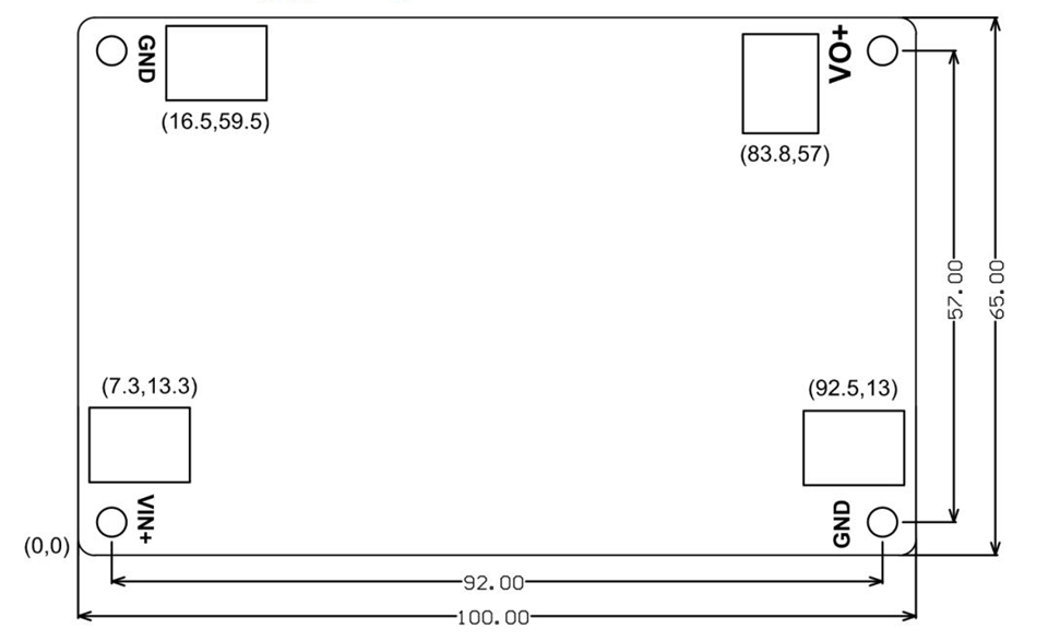
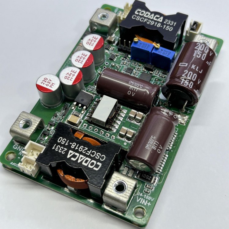
- Size: 100 x 65 x 25mm
- Net weight: 200g
Note:
1. The minimum current of resistive loads cannot be limited to 5A, while battery charging can be within 1A. It is recommended that the minimum duty cycle after current limitation be greater than 10%.
2: When the output current is 30A and the output voltage is less than 30V after long-term operation, the high output voltage and high voltage difference ratio of other high output voltages need to be reduced, and good heat dissipation must be done for overload use.
3: The situation where the startup time needs to be adjusted is when the input power supply has a longer startup time, such as when the AC adapter takes 50ms to establish full load voltage output, and the startup time of this power supply is 10ms, which may cause the AC to fail to start normally with load. It is recommended to power on first and then test with load.
4: Some parameters may be adjusted for different applications.
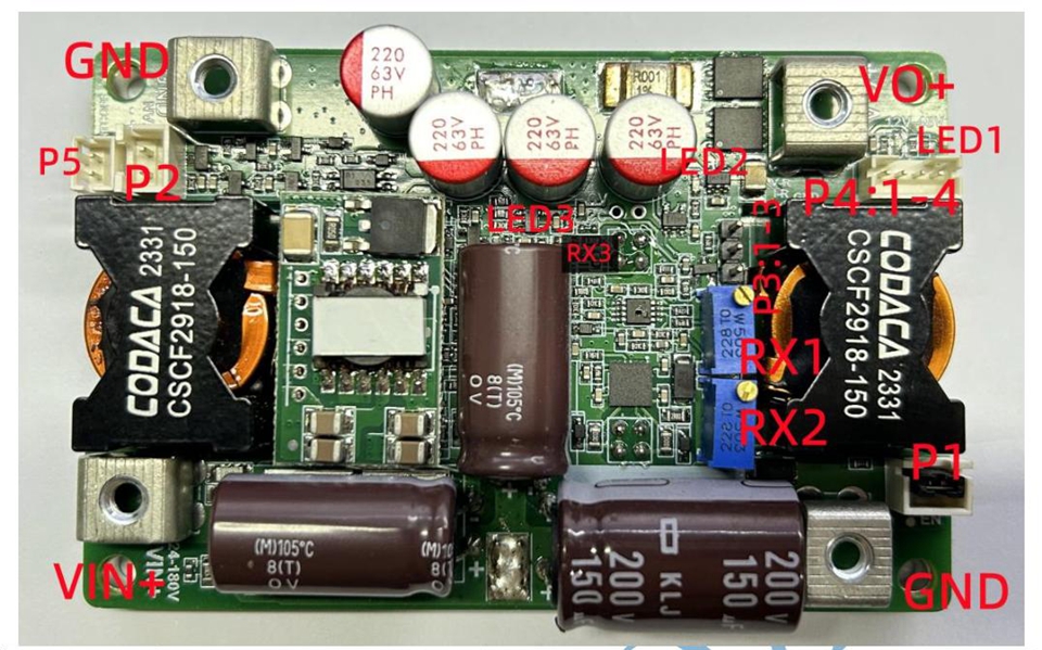
Interface Functions:
- VIN+: positive pole of power input: INPUT+; can not be connected to AC and in reverse.
- GND: power input/output negative pole; common negative.
- VO+: positive pole of power output; do not connect the positive and negative poles of the battery in reverse.
- RX1: output voltage regulation, increasing clockwise; 25 turns of potentiometer correspond to output voltage variation of 5-65V.
- RX2: output current regulation, increasing clockwise; rotating the potentiometer 25 times corresponds to a variation in output current limit of 5-35A. The specific current limit value needs to be obtained through actual measurement.
- RX3: input tracking voltage value adjustment, default cannot be used; Suitable for applications in solar panels, fuel cells, and generators, with a tracking range of 24-120V. The principle is to reduce the output current when the input voltage is lower than the set voltage. Set the voltage value V = 14335/(47+Rx). For example, if the welding resistance is 47K, input the tracking voltage of 152.5V.
- P1: EN enable interface (default power on when downside, shutdown when suspended); After the interface is pulled down to GND, the power supply will start working. It can be powered on by pulling down transistors, optocouplers, and small relays, and has strong anti-interference ability.
- P2: temperature controlled fan power supply interface (Up for - and down for +); a fan with a voltage of 12V or less and a current of 0.5A can be configured for air cooling and heat dissipation. As the power of the fan needs to be higher, it is recommended to design a well-designed air duct.
- P3-1: control signal GND; to connect the negative pole of external control signal.
- P3-2: output current control interface; The external DAC is connected to a 0-2.0V analog voltage value, which corresponds to a control output current variation of 5-35A. The formula is Iout=20*Vi, for example, if the control signal Vi=1V, the maximum output current is 20A.
- P3-3: output voltage external control interface (RX1 need to be counterclockwise to the end); if an external DAC is connected with an analog voltage value of 0-1.6V, the output voltage should be controlled to vary between 54-0V. The signal should have a certain carrying capacity, should not jitter, and should be kept away from interference. The formula is Vo=55.68-34.3*Vx. For example, control signal Vx=0V, output voltage 55.68V.
- P4: optional voltage and current display interface; optional function, can display output voltage and current on a digital tube, and can also output current signals for sampling by a microcontroller.
- P4-1: output voltage detection interface; this interface outputs voltage values, which can be used for voltage detection and must not run current.
- P4-2: auxiliary power supply 12V interface; power the display meter or provide external power of 12V/0.2A.
- P4-3: output current detection interface; detect voltage value V=0.0337*Iout, for example, output current 30A, signal value 1.01V, only used for sampling by the microcontroller ADC.
- P4-4: negative pole interface of display; It can also be used as the negative pole of the detection signal.
- LED1: working indicator; light on when powered on.
- LED2: standby indicator; light on after the input power on slow start is completed and there is output voltage.
- LED3: input tracking indicator CVIN; If the actual input voltage is lower than the set input voltage, the light will turn on. For example, if the set voltage is 72V and the current actual input voltage is ≤72V, the light will turn on.
Note:
1: Four screws must be installed and fixed before connecting the copper nose to avoid excessive stress on the board and damage to the mechanical structure of the power supply.
2: When testing this power supply, it is necessary to ensure that the input source can provide sufficient current (> 40A) to prevent the power supply from collapsing or even being damaged. Do not carry heavy loads or test complete functionality if it cannot be guaranteed.
3: The startup time of the input source must be less than the startup time of this power supply (such as using an adapter as input), otherwise it may not be able to start with load.
4: The input wire connected to this power supply must not be too long (the internal resistance of the wire must not be too high), otherwise the power supply may produce oscillations and abnormalities. Overvoltage damage to equipment or power supply caused by long wire pulse working current should be avoided.
5: If there is a diode connected in series between the input source and the power supply, there should be sufficient input voltage margin to ensure that the power supply is not damaged by overvoltage caused by instantaneous on-off.
6: Do not use the CC mode of electronic loads as the load of this power supply (it must be ensured that the input power is greater than the output power under any circumstances), it is recommended to use the CR mode. CC mode absorbs current, this power supply is limited in current, and constant current state will cause the power supply to collapse.
7: Manual MPPT is suitable for charging photovoltaic panels and requires setting the maximum power point voltage of the current photovoltaic panel. It cannot automatically track, but it is also efficient unless the characteristics of the photovoltaic panel change.
Package Included:
- 1 x Power Supply Module
- 1 x Heat Dissipation Sheet
- 1 x Cooling Fan
- 1 x Display Module