| Quantity | 3+ units | 10+ units | 30+ units | 50+ units | More |
|---|---|---|---|---|---|
| Price /Unit | $243.55 | $238.58 | $231.12 | $221.18 | Contact US |
 AD9379-A RF Evaluation Board Dual RF RX/TX Replacement for ADRV9009 Transceiver RF Board
$833.04
 USB/MIDI Dual-mode Computer Volume Adjuster Music Play Controller Compatible with Windows/Mac Systems
$81.65
 BU-5 Bluetooth Module Radio Bluetooth Adapter Unit for Yaesu FTM-150R FTM-510DR Transceiver
$55.79
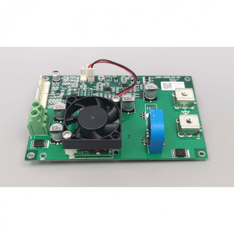
LDDH-25A5.5V-MA LED Driver Board High Voltage Low Current Laser Diode Power Constant Current Driving Module
Features:
- Suitable for driving single ended (one laser diode), double ended (two laser diodes) pump lasers, semiconductor, welding, fiber lasers, and other types of lasers. Suitable for welding, marking and other applications.
- Semiconductor laser testing, LED light-emitting diode testing, various diode testing, etc. are all applicable.
- Hall sensor.
- High speed, fully adaptive load voltage.
- No ripple.
- Efficient, air-cooled, no special heat dissipation requirements.
- Beneficial for integration.
- Four layer single board thick copper design, small size, high reliability.
Specification:
- Adaptive voltage: 5.5V, adaptive
- Rated current: 25/45/60A (optional)
- Input voltage: 12V +/- 10%, it is recommended to use 12V standard switch power supply
- Current rising/falling speed: 200us
- Size: L x W x H = 130 x 85 x 30mm
Examples of applicable products:
- All series of products for DILAS Single Bar.
- All products for DILAS Multi Bar 120W and below.
- It can drive single, two, or even three (not exceeding 5.5V) LD laser diodes, providing fast and stable constant current with fully adaptive voltage. The specific factory default rated current can be specified by the user, such as 25A, 45A, or 60A. High speed power supply, current rise/fall time <200us. Suitable for welding, marking and other applications! Semiconductor laser testing, LED and various diode testing. Internal and external control selection, which means two analog inputs. Ideal power supply for end pumps, side pumps, semiconductors, welding, and fiber lasers, with a wide range of applications.
- All products for DILAS below 120W are suitable (high current laser diodes). The ideal power supply for coherent and similar products.
- Whether it is 25A, 45A, 60A, single or double LD, it is suitable. Of course, there is no problem with LDs rated below 25A. The product is essentially a high-quality constant current source, suitable for various loads within the rated parameters.
Interface Definition:
- PVDD: power input port/7.5mm wiring terminal (note: the power supply voltage range is 8-14V)
- AN2/POT: second channel analog input terminal, can be connected to potentiometer or analog/2510-3P socket
- CHSW: channel (internal and external control) selection/2510-2P socket, and if not connected, use the analog input of the CTL interface by default
- CTL: control terminal/2510-6P socket
- LD: output port/φ5 high current wiring terminal
A: Connect the positive pole of the load LD
K: Connect the negative pole of the load LD
Different Application Configurations:
- For applications that only require one analog signal to directly control the output current of the driver board, only the CTL interface can be used to control the driver board, and AN2/POT and CHSW interfaces are not connected to any signals.

- For applications that require internal and external control, such as a power box that has both local signals and external analog signal input ports. Local signals are usually provided by potentiometers or generated by local micro-controllers, while external control signals are provided by the user of the enclosure. At this point, CTL's IC can be used to connect external analog signals, AN2/POT can be directly connected to a 10K (1K-100K is fine) potentiometer, or a local analog signal generated by the IC2 microcontroller, and then CHSW's SW can be used to switch between internal and external control.

- For applications that require fast modulation of current (such as power switches in fiber lasers), CTL's IC input current signal and AN2/POT's IC2 input threshold current signal can be used, and then TTL signal can be directly used to output CHSW's SW to modulate the current. Of course, direct modulation of analog signals, that is, using only ICs with rapidly changing analog inputs, is also possible.

- Note: during modulation, it is generally not adjusted between 0A and the operating current, but rather from the threshold to the operating current. If the current is 0A, it is not good for the laser diode first, because without a maintained threshold current, the thermal shock will be greater, which is unfavorable for the laser diode. Secondly, the debugging performance is also poor, which not only prolongs the time for the current to rise, but also generates extra response time, thereby reducing the modulation speed.
Package Included:
- 1 x LED Driver Board