| Quantity | 3+ units | 10+ units | 30+ units | 50+ units | More |
|---|---|---|---|---|---|
| Price /Unit | $235.35 | $230.54 | $223.34 | $213.73 | Contact US |
 STK428-640 HiFi Power Amplifier Board 200Wx2 Class D High Power Amplifier Module PWM CMOS Logic Level Audio Input
$36.49
 OPS200 Dual Operational Amplifier 60mA Class A Op Amp for Low Impedance Circuit Amplifier and Drivers
$15.79
 PAP-HD1-XLR Hi-End Fully Balanced Preamplifier Board Support Remote Control Replacement for HDAM Circuit
$84.53
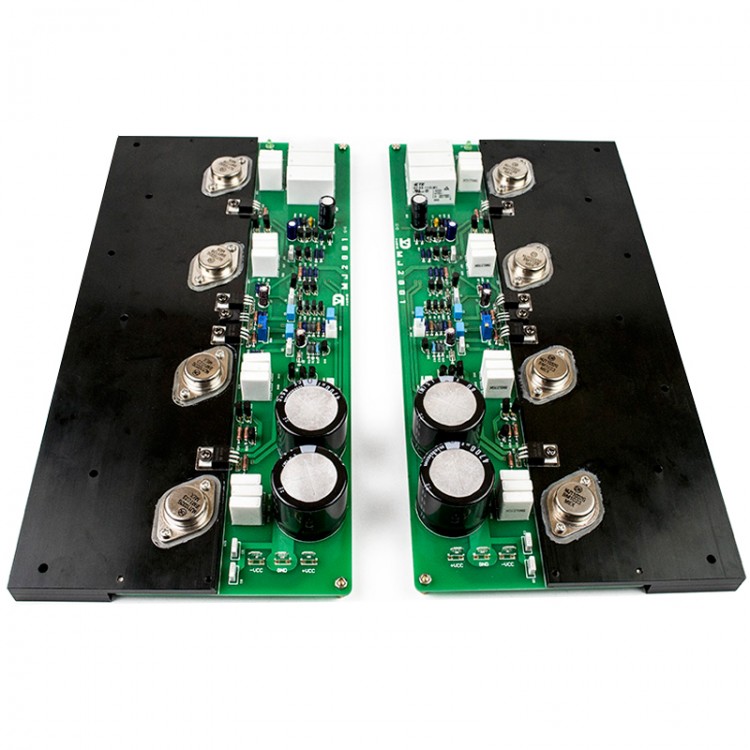
MJ2001 50W Amplifier Board MJ11032/33 HiFi Class A Stereo Power Amp Board CDE Capacitor Heat Conduction
Specifications:
Maximum output power: 180W / 8 ohms, 350W / 4 ohms
Maximum supply voltage: + -60V (main power), speaker protection Power: AC 12V -15V
Harmonic Distortion: <0.001% 10W / 8 ohms; <0.05% 100W / 8 ohms
Frequency response: 1Hz-200KHz
Damping coefficient: > 200
Signal to noise ratio: > 96dB
Conversion rate: > 35V /μS
Input impedance: 33.2K
Gain: 31dB (34x)
Features:
1. The circuits at all levels are designed in Class A state (the working state of the output tube is adjustable), which effectively improves the fax degree of the voice.
2. The open loop voltage gain design is relatively low, only more than 60dB, which makes the sound of the power amplifier more realistic and vivid.
3. The output stage adopts inverted Darlington circuit output, which effectively improves temperature stability and reduces distortion.
4. The amplifier part of the power amplifier adopts a set of power supplies, which is convenient to use (the protection circuit needs to be connected to a set of power supplies).
5. There is a complete protection circuit, with over-current, output short-circuit and DC protection functions, using original American TE Tyco high-quality relays. Using 3 high-current relays per channel can better over-current, but also effectively extend the life of the relay.
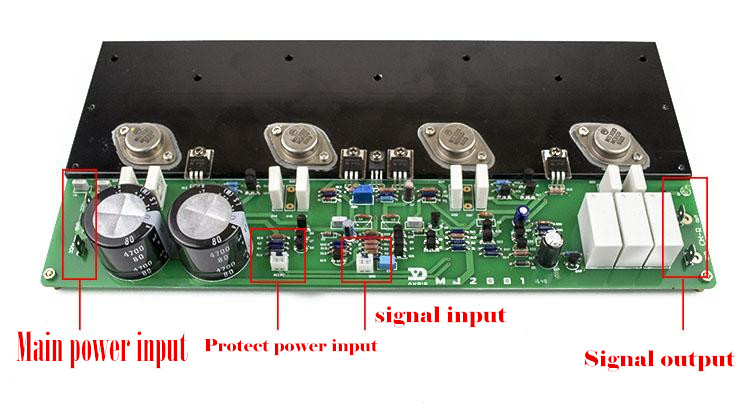
6. The power input and signal output of the power amplifier use standard connectors, which can be connected by 6.3mm plug springs without welding, very convenient.
7. The power amplifier adopts high-precision and stable DALE resistors.
8. Low distortion rate, good thermal stability.
Wiring diagram and debugging method:

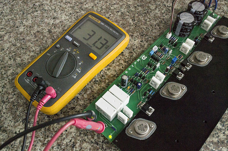
Mid-point voltage test: The mid-point voltage of this board is free of adjustment. In a static state, no signal is input, and the DC voltage at the output terminal is measured. If it is normal, it is below 50mv, as shown in the following figure:

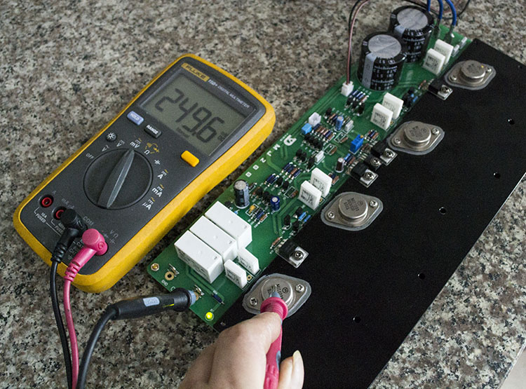
Static current debugging: connect the black meter pen to the signal output terminal, and the red meter pen to measure the C pole of the power tube, which is the outer shell of the power tube. The measured voltage is the voltage of the non-inductive resistance, and then converted into current according to Ohm's law. Please make adjustments according to actual usage. The higher the voltage, the greater the quiescent current, the greater the heat generation, and vice versa. This is only for testing. Please add a heat sink during actual use. The connecting aluminum plate is far from enough for heat dissipation.
The quiescent current test result in the figure below: 249.6MV÷0.5Ω (two 1 ohms in parallel, ≈500MA, the total quiescent current of the power tube is 1A.

Package List:
1 Pair of Amplifier Board