
| Quantity | 3+ units | 10+ units | 30+ units | 50+ units | More |
|---|---|---|---|---|---|
| Price /Unit | $126.65 | $124.06 | $120.18 | $115.01 | Contact US |
MX-S3 SDR Transceiving Switch Radio Spectrum/Secondary Receiver Adding RF Switch for FT-891/FT818/IC7100
Description:
- The MX-S3 is designed to add a second receiver to a transceiver or to connect an SDR software receiver for real-time spectrum analysis. This switch features high isolation and offers two transmission control methods: keying and RF sensing control. It also includes a receiver protection circuit and provides three AUX auxiliary control output interfaces, which can be used to control receiver muting, power amplifiers, and other external devices.
Specification:
- Power Supply: 12V±20%, 500mA
- Impedance: 50Ω
- Isolation: -70dB
- Insertion Loss: 0.15dB
- Power handling: 200W
- Operating frequency: 0.5 - 440MHz
- AUX1/AUX2 load capacity: 100mA/30V. These interfaces are controlled by MOSFET transistors and provide a low level during transmission.
- AUX3 interface load capacity: 1A/30V. This interface is controlled by a relay, with jumper-selectable normally open (NO) and normally closed (NC) states.
Package Included:
- 1 x SDR Transceiver Switch
Using Instruction:
1. Connect the DC interface to a 12V/0.5A DC power supply.
2. Turn on the POWER switch on the panel. The POWER indicator will light up, and the TX light will also illuminate.
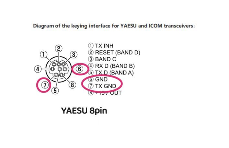
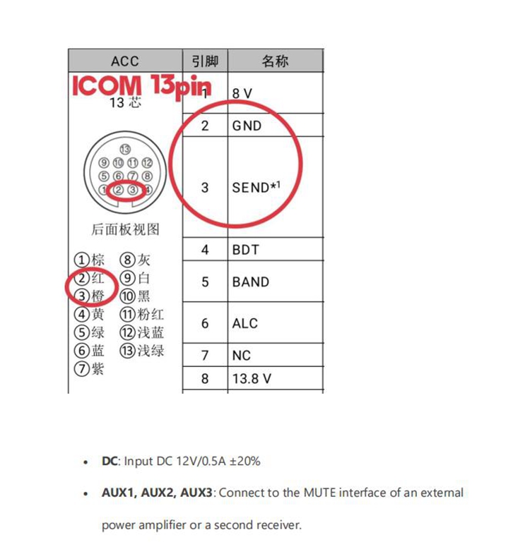
3. Insert the 3.5mm control cable plug into the SEND interface, and connect the other end to the SEND keying interface of the transceiver. At this point, the TX light will turn off, and the RX light will illuminate.
4. If using RF sensing for transmit/receive control, still insert the 3.5mm plug of the control cable into the SEND interface, but leave the other end unconnected. Additionally, short the RF SENSE jumper on the internal PCB and adjust VR1 to set the appropriate delay time.
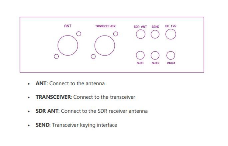
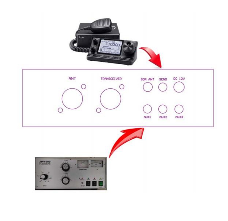
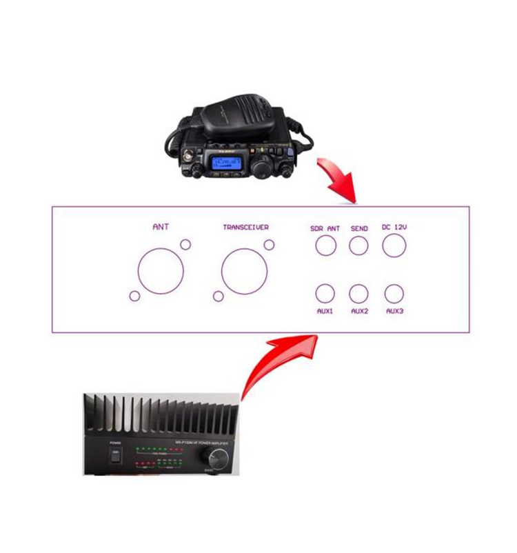
5. Connect the SDR ANT interface to the receiver antenna port, the ANT interface to the antenna, and the TRANSCEIVER interface to the transceiver.
6. AUX1/2/3 can be connected to the MUTE interface of a power amplifier or receiver. These interfaces provide a low level during transmission (AUX3 can be configured as normally open or normally closed via an internal jumper).
In the case where the transceiver needs to be connected to a power amplifier for use (if there is no need to connect it to a power amplifier for use, please ignore this).
Example 1:
Example 2:
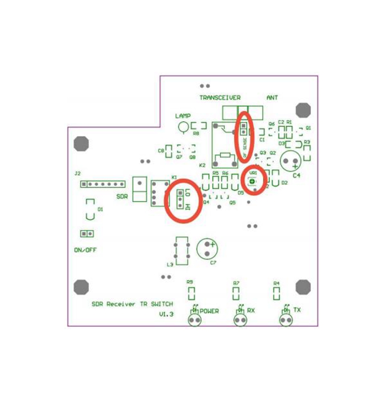
RF SENSE: If using RF sensing control, short this jumper. Remove the jumper when using keying control. If the radio frequency sensing function control is not required, this jumper should be removed to improve the SWR (Standing Wave Ratio) and reduce the receiving loss.
VR1: Adjusts the transmit/receive switching delay time, adjustable from 40ms to 3s. Turning counterclockwise increases the delay time.
LO/HI: Jumper setting for the AUX3 interface. Shorting LO provides a low level during transmission (relay internal contacts close). Shorting HI causes the relay contacts to open during transmission.