| Quantity | 3+ units | 10+ units | 30+ units | 50+ units | More |
|---|---|---|---|---|---|
| Price /Unit | $31.30 | $30.66 | $29.70 | $28.43 | Contact US |
 Blue Light Desktop Turbo Fan Creative Jet Fan Engine Built-in Ultrasonic Atomization Device with 50ML Water Tank
$69.64
 Red Light Desktop Turbo Fan Creative Jet Fan Engine Built-in Ultrasonic Atomization Device with 50ML Water Tank
$69.64
 16PCS Number Sign No.1 to No.16 Wireless Walkie Talkie Silicone Rubber Number Belt with Storage Bag
$21.83
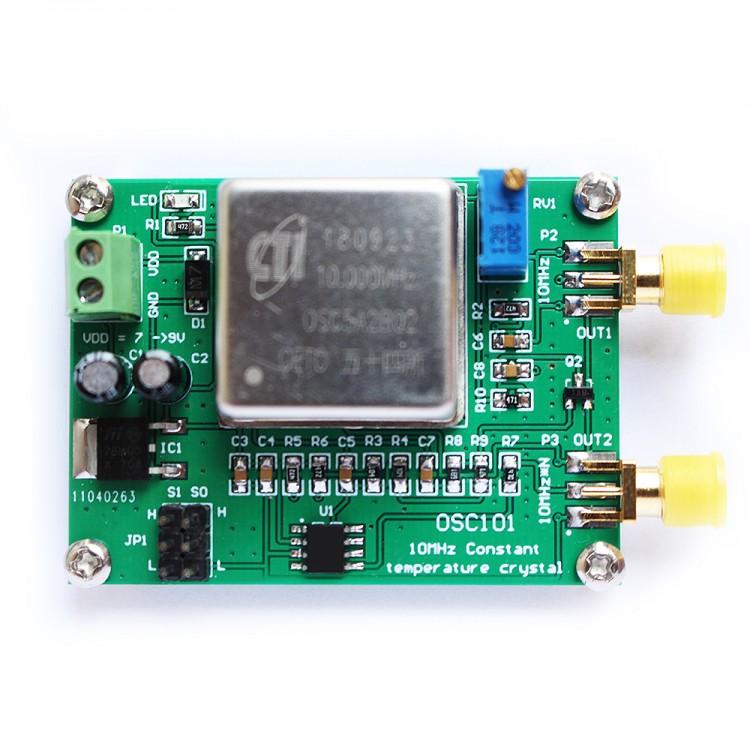
- This module outputs the frequency accuracy of the 10MHz signal (+/-200ppb), has two signal outputs, and one is a standard 10MHz signal.
- The other is a 10MHz multiplier signal. The multiplier signal has 9 selection frequencies, which are 2X, 3X, 3.125X, 4X, 5X, 5.3125X, 6X, 6.25X, 8X.
- The different multipliers are selected by the JP1 jumper pin. Correct the deviation of the 10Mhz output frequency (+/-2.0ppm) with the RV1 potentiometer.
1. P1: Power input interface; (7~9V).
2. P2: 10MHz signal output interface; (10Mhz amplitude: 3Vpp) SMA interface
3. P3: N frequency output interface of 10MHz signal; (N*10Mhz amplitude: 5Vpp) SMA interface
4. RV1: Correct the deviation of the 10Mhz output frequency (+/-2.0ppm)
5.JP1 jumper needle selection
S1=0,S0=0, OUT = 4X
S1=0,S0=M, OUT = 5.3125X
S1=0,S0=1, OUT = 5X
S1=M,S0=0, OUT = 6.25X
S1=M,S0=M, OUT = 2X
S1=M,S0=1, OUT = 3.125X
S1=1,S0=0, OUT = 6X
S1=1,S0=M, OUT = 3X
S1=1,S0=1, OUT = 8X
0 = connect directly to ground(L)
1 = connect directly to VDD(H)
M = leave unconnected(floating)
Specification:
- Length X width X height:56mm*45mm*25mm