| Quantity | 3+ units | 10+ units | 30+ units | 50+ units | More |
|---|---|---|---|---|---|
| Price /Unit | $259.10 | $253.81 | $245.88 | $235.31 | Contact US |
 M5Stack Atomic Echo Voice Recognition Base ES8311 Mono Audio Decoder MEMS Microphone for M5 Atom Series
$15.79
M5Stack Atomic Echo Voice Recognition Base ES8311 Mono Audio Decoder MEMS Microphone for M5 Atom Series
$15.79
 M5Stack LLM Offline Large Language Model Inference AI Module Set AX630C Processor 4GB LPDDR4 32GB EMMC5.1
$75.03
M5Stack LLM Offline Large Language Model Inference AI Module Set AX630C Processor 4GB LPDDR4 32GB EMMC5.1
$75.03
 M5Stack Atomic Battery Base Portable Power Base Built-in 200mAH Battery ETA9085E10 Boost Chip
$15.79
M5Stack Atomic Battery Base Portable Power Base Built-in 200mAH Battery ETA9085E10 Boost Chip
$15.79
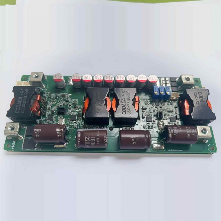
Parallel Version High Voltage DC Buck Converter FPV Power Supply Board with Display Module DC24-130V In DC5-54V Out 45A 2000W
Precaution:
- Do not connect the battery for charging. An ideal diode must be added to prevent reverse charging, and the positive and negative terminals of the battery must not be connected in reverse.
- Long term output short circuit is prohibited. Prolonged short circuit with high current can damage the ideal diode, and can also cause voltage spikes or even negative voltage due to instantaneous high current, leading to DC damage.
Typical Performance (YF-BK130V45A-D):
- Non-isolated synchronization buck power supply, constant voltage and current.
- Wide input DC24 - 130V, output DC5 - 54V
- Peak efficiency: >98.0%
- Protection: overcurrent regulation, short circuit protection self-recovery, over temperature protection, temperature-controlled fan.
- Remote ON/OFF, status indicator
- Adjustable input voltage and current
- High voltage regulation accuracy and fast transient response.
- Suitable for fixed MPPT function of fuel cells and solar panels.
- Input supports high voltage hot plugging.
- Aluminum substrate with high thermal conductivity design and natural heat dissipation capacity up to 15W (ambient temperature 25℃).
- Constant frequency working MEI facilitates prediction.
- Power can reach over 2.0KW (output >48V)
- Unless otherwise specified, all tests were conducted at 120V input and 48V output, intermittent mode, pure resistive load, and 25 ℃ room temperature.
Absolute Maximum Rating:
- Input voltage: -1 ~ 150V
- Output voltage: -1 ~ 60V
- Power off interface (EN): -0.7 ~ 30V
- External voltage control interface: 0 - 5V
- External current control interface: 0 - 5A
- Fan interface current limit: 0.3A
- Storage temperature: -40 ~ 125℃
- Aluminum substrate and power pin withstand voltage: 300 - 500V (non-isolated)
- Maximum torque of screw terminal: 2 - 3N.m (Do not apply excessive upward stress.)
- Potentiometer rotation life: 200 times
Recommended Using Parameter:
- Input voltage: 36.0 - 130.0V
- Input current: 30.0 - 35.0A
- Output voltage: 12.0 - 54.0V
- Output current: 0 - 45.0A (typ. 40.0A)
Input Characteristics:
- Input working voltage range: 24 - 130.0V
- Input tracking voltage adjustment range: 24 - 120V
- Input under-voltage protection adjustment range: 19 - 120.0V
- Undervoltage protection hysteresis value: 0.96*Vu - 1.04*Vu (Vu: setting undervoltage value)
- Input current operating range: 20.0 - 30.0A
- Input current limit value: typ. 40A
- No load input current value: 40.0 - 60.0mA (typ. 50.0mA), (standby power consumption about 2-3W)
- Shutdown current (complete machine shutdown): 1.0 - 1.5mA (1.2mA)
- Input reverse protection: not supported
- Hot swappable voltage: support voltage input of full range
Output Characteristics:
- Output voltage range: 5.0 - 54.0V (typ. 28.0V)
- Output current working range: 40.0 - 48.0A (typ. 40.0A), (VO of 45A < 30V)
- Output current adjustment range: 5.0 - 48A
- Output current limit: 48.0 - 49.0 A
- Short-circuit current: 48 - 49A (continuous, equal to current limit value)
- Output voltage regulation rate: 0.96*Vu - 1.04*Vu (Vu: setting undervoltage value)
- Output voltage ripple noise (PK-PK): 40 - 60mV (typ. 50mV) (120V to 28V/45A)
- Output voltage ripple noise (PK-PK): 45 - 65mV (typ. 55mV) (120V to 48V/45A)
- Input and output differential voltage (lo=40A): 1.0 - 3.0V (typ. 2.0V), (it is recommended to use < 95% duty cycle)
Dynamic Characteristics:
- Load step 120V to 28V/45A: 1.6 - 1.9V (typ. 1.8V), (0% - 100% Iout)
- Recovery time: 0.3 - 0.7ms (typ. 0.5ms), (<2% Vout)
- Output voltage overshoot: 1.4 - 1.6V (typ. 1.5V), (load 100% - 0%)
- Recovery time: 10 - 30ms (typ. 20ms), (<1% Vout)
- Load step 120V to 48V/45A: 1.8 - 2.2V (typ. 1.9V), (0% - 100% Iout)
- Recovery time: 0.4 - 0.8ms (typ. 0.6ms), (<2% Vout)
- Output voltage overshoot: 1.2 - 1.6V (typ. 1.4V), (load 100% - 0%)
- Recovery time: 5 - 20ms (typ. 10ms), (<1% Vout)
- Slow start time (related to VIN): 1.0 - 5.0s (typ. 2.0s) (power on to establish output voltage)
- Establishment time of output voltage (gradient): 120 - 150ms (typ. 130ms)
Conversion Efficiency:
- 120V to 29V (1300W): 96.2 - 96.4% (typ. 96.3%)
- 120V to 48V (2100W): 97.7 - 97.9% (typ. 97.8%)
- 80V to 48V (2100W): 98.5 - 98.7% (typ. 98.6%)
Other Characteristics:
- Switch frequency: 155 - 165kHz (typ. 160kHz)
- Boost voltage differential ratio: 4 - 15 times (Vo/Vin)
- EN enables the effective voltage to be turned off: 0 - 1.0V (typ. 0.7V)
- Vo external control effective voltage: 0 - 2.0V (RX1 need to be counterclockwise to the end)
- Voltage control signal load capacity: 2 - 5mA
- Iout external control effective voltage: 0 - 2.0V
- Load capacity of current control signal: 5 - 10mA (typ. 10mA) (RX2 need to be clockwise to the end)
- Fan terminal power supply voltage: 10 - 10.5V (typ. 10.2V)
- Fan terminal power supply current: 0.2 - 0.5A (typ. 0.3A), (no short-circuit allowed)
- Over temperature protection value: 85℃ ~ 95℃ (aluminum board temperature)
- Power supply operating temperature: -40℃ ~ 85℃ (typ. 25℃)
- Electrolytic capacitor working withstand temperature: 105℃ (pay attention to VIN capacitor heat dissipation)
- Storage temperature: -40℃ ~ 85℃ (typ. 25℃)
- Storage humidity: 5 - 95%RH (non-condensing)
- Cooling method: natural heat dissipation with a loss of less than 15W, and heat dissipation or air cooling with a loss of over 20W. (25℃ environmental temperature)
- Size: 190 x 80 x 23mm
Note:
1. The minimum current of resistive loads cannot be limited to 5A, while battery charging can be within 3A. It is recommended that the minimum duty cycle after current limitation be greater than 10%.
2: When the output current is 48A and the output voltage is less than 30V after long-term operation, the high output voltage and high voltage difference ratio of other high output voltages need to be reduced, and good heat dissipation must be done for overload use.
3: The situation where the startup time needs to be adjusted is when the input power supply has a longer startup time, such as when the AC adapter takes 50ms to establish full load voltage output, and the startup time of this power supply is 10ms, which may cause the AC to fail to start normally with load. It is recommended to power on first and then test with load.
4: Some parameters may be adjusted for different applications.
5: Four screws must be installed and fixed before connecting the copper nose to avoid excessive stress on the board and damage to the mechanical structure of the power supply.
6: When testing this power supply, it is necessary to ensure that the input source can provide sufficient current (> 50A) to prevent the power supply from collapsing or even being damaged. Do not carry heavy loads or test complete functionality if it cannot be guaranteed.
7: The startup time of the input source must be less than the startup time of this power supply (such as using an adapter as input), otherwise it may not be able to start with load.
8: The input wire connected to this power supply must not be too long (the internal resistance of the wire must not be too high), otherwise the power supply may produce oscillations and abnormalities. Overvoltage damage to equipment or power supply caused by long wire pulse working current should be avoided.
9: If there is a diode connected in series between the input source and the power supply, there should be sufficient input voltage margin to ensure that the power supply is not damaged by overvoltage caused by instantaneous on-off.
10: Do not use the CC mode of electronic loads as the load of this power supply (it must be ensured that the input power is greater than the output power under any circumstances), it is recommended to use the CR mode. CC mode absorbs current, this power supply is limited in current, and constant current state will cause the power supply to collapse.
11: Manual MPPT is suitable for charging photovoltaic panels and requires setting the maximum power point voltage of the current photovoltaic panel. It cannot automatically track, but it is also efficient unless the characteristics of the photovoltaic panel change.
Package Included:
- 1 x Power Supply Module