| Quantity | 3+ units | 10+ units | 30+ units | 50+ units | More |
|---|---|---|---|---|---|
| Price /Unit | $92.42 | $90.54 | $87.71 | $83.94 | Contact US |
 265W 3CH Buck-Boost Fast Charger Full Protocol Fast Charging Module Desktop Charger for QC3.0 QC5+
$41.44
265W 3CH Buck-Boost Fast Charger Full Protocol Fast Charging Module Desktop Charger for QC3.0 QC5+
$41.44
 200W Charger 2CH Fast Charging Module (Main Unit & 1m Data Cable for Type-C + Apple & Power Supply)
$65.08
200W Charger 2CH Fast Charging Module (Main Unit & 1m Data Cable for Type-C + Apple & Power Supply)
$65.08
 200W Charger 2CH Fast Charging Module (Main Unit & 1m Type-C+Type-C Data Cable & Power Supply)
$65.08
200W Charger 2CH Fast Charging Module (Main Unit & 1m Type-C+Type-C Data Cable & Power Supply)
$65.08
POWER-Z KM002C 0-50V 0-6A USB C Tester w/ USB PD Decoy Board USB Connector for Aging Loading Tests
POWER-Z KM002C
User Manual:
https://docs.google.com/document/d/1T55UeixUNN9La3tzAF0jO45Snw_rrd9RVGt3XQeRIM8
Features:
- CHARGERLAB POWER-Z fast charge tester
-
Processor for ARM Cortex-M4: 192MHz operating frequency, 32bit
processor and Thumb-2 instruction set. Built-in DSP; supports
floating-point operations
- 20bit ADC; 4MB large FLASH; resistant to 50V high voltage
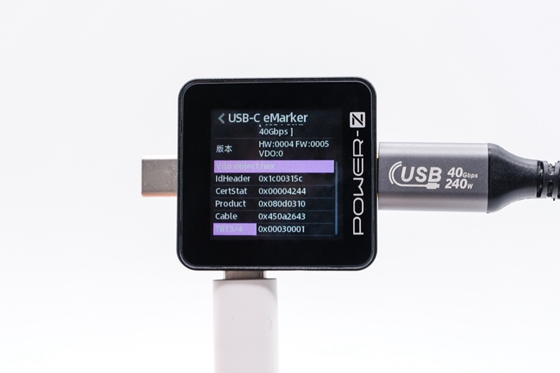
- E-marker test function: PDO test for Apple 140W charger, supporting 5V, 9V, 15V, 20V and 28V
- Protocol detection: PD3.1, QC4, QC5, SCP, FCP, AFC, VOOC, SuperVOOC, VIFC, EPR and UFCS
- Mini size: portable to carry and easy application
-
Support USB PD3.1: The new USB PD3.1 fast charging standard will
support voltage output up to 48V, and the charging power will be
simultaneously increased to 240W
- High brush and high brightness, the screen is upgraded again. 1.3" IPS screen, resolution 240x240 and 1:1 screen ratio
-
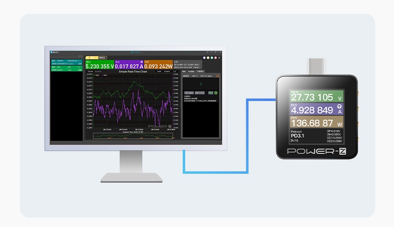
Powerful host computer: visualized graphical interface display; USB PD
handshake protocol analysis; online viewing of charging power; local
storage of charging data; online update of the host computer; support
for the multi-open function of the tester
Parameters:
- Model: KM002C
- Dimensions: 36 x 37 x 8mm/1.4 x 1.5 x 0.3"
- Screen size: 1.3"
- Screen material: IPS
- Screen Resolution: 240x240
- Language: English/Chinese
- Test interface type: Type-C
- Number of test ports: 2C port
- Operation type: button
- Independent power supply, computer communication port: Type-C (5V) Name: HID
- Interface internal resistance: about 28mΩ
- Typical working current: 8~25mA
- Voltage accuracy: 0.00002V
- Current accuracy: 0.000003A
- Voltage range: 0-50V
- Current range: 0~6A
- Number of offline recording groups: 4MB built-in storage
- Maximum number of sets of capacity energy: 50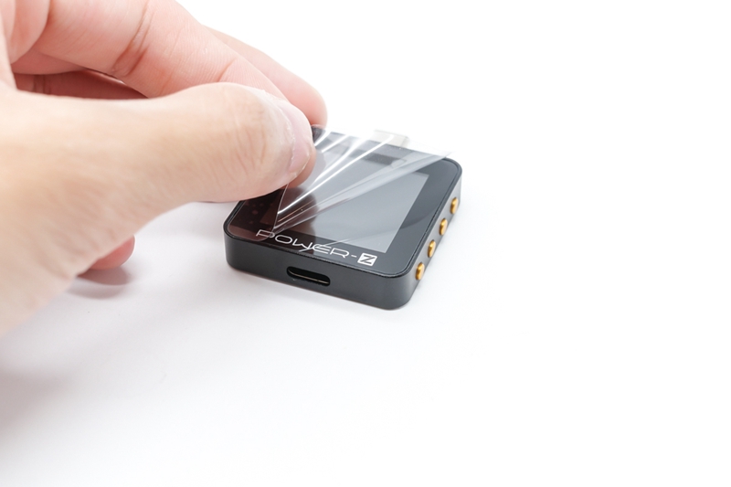


USB PD Decoy Board
Description:
The
140W 28V PD decoy test board is suitable for factories with many
development needs and large quantities of products. It supports spoofing
PD packets in EPR mode, with a maximum withstand voltage of 30V, and
can support up to 28V EPR packets. Support 5V, 15V, 20V, 28V output
indicator display. At present, it can meet the development and testing
needs of most USB PD fast charging products.
With
a super compact design, the size of its entire PCB board is only 1.6x1"
(40x25mm). In addition, the components on the PCB board are also very
simple, and the core device IP2726 chip for INJOINIC is used.
5
LED indicators on the board represent 5 groups of different PD0s. 4
buttons represent PD "+" and "-" adjustment, switching each PD0 and
adjusting PPS "+" and "-". At present, it can only adjust the PD
function, so that the USB PD power supply device can output the set
voltage.
Button Description:
* Button +: Used to switch
the next PD package. Press the button once to request the next PD
packet output. If the current PD package is the last PD package,
pressing this button will request the output of the current PD package
again.
* Button -: Used to switch the previous PD packet, press the
button once to request the output of the previous PD packet. If the
current PD package is the first PD package, pressing this button will
request the output of the current PD package again.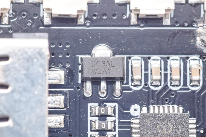
SC33LW2A1 voltage-regulator tube
USB interface: can be connected to a load for testing
IP2133 Emarker Connector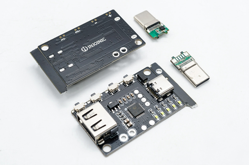

Connection Wire Selection:
* Cut a section of any 5A wire
* Wiring method: red wire: → power supply+ (outside); metal-clad wire: → power supply ground; white wire: → CC wire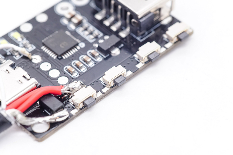
Welding of power supply ground wire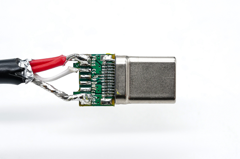
Wiring method: red wire: → power supply+ (outside); metal-clad wire: → power ground; white wire: → CC wire
Complete connection display and the use process:
1.
Make sure that the Src terminal is working normally, the C port is the
input terminal, and connect to the output terminal of the Src terminal
through the cc line or other connecting lines. If the Src terminal
supports PD, it will automatically enter the PD mode after connection;
the A port is the output terminal, which can be used to connect to the
load for on-load testing.
2. If there is a PD package on the Src side, use the "+" or "-" button to switch the PD package.
*
Note: When TYPE-C is connected to the adapter USB, please not connect
the output end of the non-test equipment to avoid damage to the
equipment.
For
demonstration, we connected a POWER-Z KM002C to the input to display
the voltage. After connecting the PD decoy to the PD charger, press the
button to adjust to 28V decoy mode. When the output is less than 15V,
LED1 will be on; when the output is greater than or equal to 15V, LED1
and LED2 will be on; when the output is greater than or equal to 20V,
LED1, LED2 and LED3 will be on; when the output is 28V, LED1, LED2, LED3
and LED4 will light up.
Decoy on-load operation; can also be used for aging test
Package Included:
- 1 x USB C Tester
- 1 x PD Decoy Tester Board
- 1 x USB Connector
Note:
- The PD decoy board should be used with cable; if you have a PD3.1 wire, it can also be used at the type-c interface.
- Other items pictured are not included, for demonstration purposes only. Thank you for your understanding!


