| Quantity | 3+ units | 10+ units | 30+ units | 50+ units | More |
|---|---|---|---|---|---|
| Price /Unit | $25.47 | $24.95 | $24.17 | $23.13 | Contact US |
 Tarot TL1901 Carbon Fiber Drone Mantis Claw Unpowered Drone Claw Gripper for Unmanned Aerial Vehicle
$36.28
 Tarot 60W TL3301 Drone Searchlight Dimmable Drone Search Light for 1" Diameter Arm Drone Multi-Rotor
$132.15
 TAROT TL2962 Drone Dispenser Drone Thrower Load 20KG/44.1LB for Multi-Axis Multi-Rotor Aircraft
$56.21
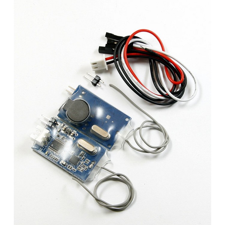
DLD280 Remote Wireless Battery Voltage Alarm for Helicopter, Multicopter, FPV 450 550
Remote/Wireless Battery Voltage Alarm DLD280
Features:
- This is the wireless battery voltage checker/alarm, it contains two modules TX and RX, the TX is mounted on board (on the aircraft), and when the monitored battery voltage is low, then the RX (mounted around you on ground) will sound the alarm.
- It enables you to monitor the on-board battery voltage.
Specifications:
- Operating Voltage: 4-9.6V
- Alarm Voltage range:3.3V-50.4V(LIPO 1S-12S)
- Weight: 2g
- Wire Length:17cm
Remote/Wireless Battery Voltage Alarm DLD280
- Item NO: DLD280
Features:
- 1 Indicate the voltage value and the system will give alarm beep when voltage is low.
Specs:
- Operating Voltage: 4-9.6V
- Alarm Voltage range:3.3V-50.4V(LIPO 1S-12S)
- Weight: 2g
- Wire Length:17.2mm
- Setting up Alarm value:
- Three Degree low voltage alarm can be set – very low, Low, and close to low voltage value.
- 1. Press button and give power to the RX board while the LED keep light.
- 2. Press the button and the one Beep means very low voltage value alarm
- confirmed ( alarm voltage range is 3.3V each cell )
- 3. Press the button again two Beeps means middle voltage value alarm confirmed ,(middle voltage range is 3.5V each cell)
- 4. Press the button third time three Beeps means the High voltage value alarm confirmed (the voltage range is 3.7V each cell)
- Wait for 3 seconds after each step there will be One beep alarm and LED
- keep light, then alarm voltage value accomplished.
- Reference voltage alarm algorithm
(Very low voltage: 1S:1*3.3=3.3V, 2S:2*3.3=6.6V, 3S:3*3.3=9.9V,…)
(Low voltage : 1S:1*3.5=3.5V, 2S:2*3.5=7V, 3S:3*3.5=10.5V,…)
(close to voltage: 1S:1*3.7=3.7V, 2S:2*3.7=7.4V, 3S:3*3.7=11.1V,…)
- The RX board will alarm when real voltage drop to set value
- Communication method between TX and RX Board:
1.Give power to the TX Board, the LED will slow flash
2.Give power to the RX Board and LED will slow flash
3.After 5 seconds the Rx board will Beep, the LED on TX Board will keep light ,the LED on RX Board flash quickly it means connecting accomplished.
4. If LED on RX Board off means no signal or wrong connecting.
5. If one board power be cut, another board should be give power again.
Normal Use:
1. First please setting up alarm value on RX board, once set it can be stored.
2. Connect Testing battery to TX Board. Then connect power battery to supply
power to the TX board. This is very important
3. There will be one Beep after giving power to RX Board, it means connecting
accomplished and the system can work normally.
4. RX board will alarm by beep loops when the testing battery voltage drop
reference value that set on setting up step.
Notes: the battery should be full charged.
Including: one TX board and one RX Board
Includes:
- 1 x RX module
- 1 x TX module
- 1 x set of cables