| Quantity | 3+ units | 10+ units | 30+ units | 50+ units | More |
|---|---|---|---|---|---|
| Price /Unit | $29.02 | $28.43 | $27.54 | $26.35 | Contact US |
 Proxmark3 PM3 RDV2 + 7.0 Software ID/IC Card Copier RFID Duplicator Reader Support Dual Frequency Card
$107.94
 Smart Door Lock Deadbolt Lock Supports Fingerprint + Password + IC Card + Tuya APP + Key + Gateway
$74.98
 Smart Door Lock Deadbolt Lock Supports Fingerprint + Password + IC Card + Tuya APP + Key to Unlock
$59.92
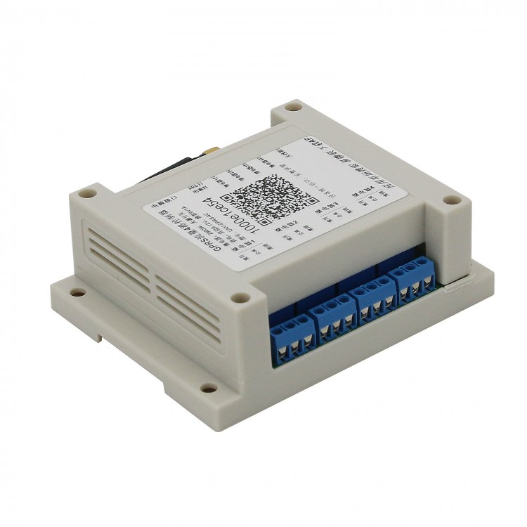
RTU-UNV-GSM-4C GSM Remote Control Switch GSM Gate Opener 4 Channel Relay Module GSM Controller
Applications:
Farmland irrigation, greenhouse, server room, pet feeding, oxygen pump, roller shutter and the like.
Package Included:
- 1 x Set of 4CH Relay Module
Note:
- Other items pictured or mentioned bellow are not included, for demonstration purposes only. Thank you for your understanding!
SMS & CALL Controller 4-Channel Instructions-V1.0:
Hardware Description: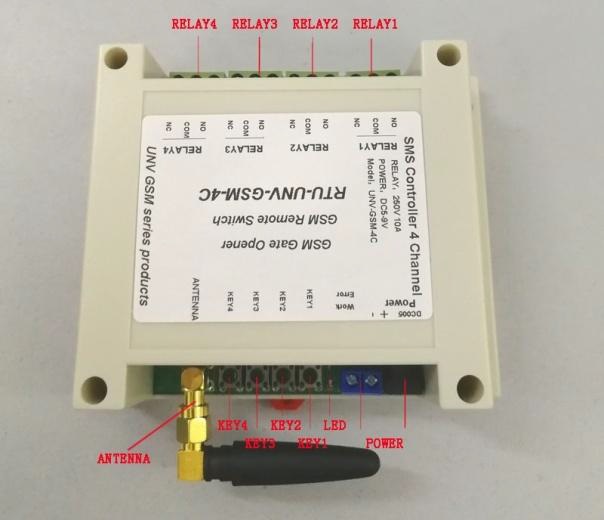
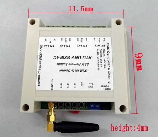
Working frequency: GSM 850MHz, EGSM 900MHz, DCS 1800MHz and PCS 1900MHz.
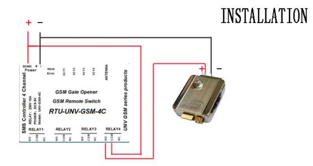
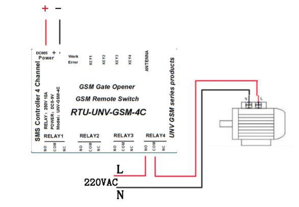
Power supply interface: Power supply voltage: 5V-12V. When using 9V or less power supply, the current must be guaranteed 1.5A or above.
Relay interface: The output is the passive switch quantity. Using 250V 10A relay, the maximum power is 2500W, you can directly operate most of the electrical appliances on the market.
SIM Card Socket (Inside the shell): Insert micro SIM card when system powered off.
Switch quantity interface (Inside the shell: SIG): XH2.54-2P. When the two pins are connected, it will trigger the SMS alarm.
Keys: Press the keys can change the status of corresponding relay when controller is power on. Press key1 when device is power off, then power on, and press the button for 3 seconds, the controller will be back to factory setting. And the led indicators will show this status.
LED interface: There are 2 LED lights named work and err. LED indicators state corresponds to the equipment working conditions are as follows, each column is one state.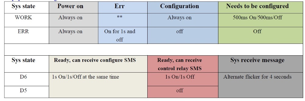
SMS Command Instructions:
All settings or control command must be sent after the equipment is in the status of ldquoReady, can receive configure SMSrdquo or ldquoReady, can receive control relay SMSrdquo. The device configuration information is saved in the device. The replacement of the SIM card does not need to be reconfigured again.
To facilitate the following example, the device code is unified to 123456.
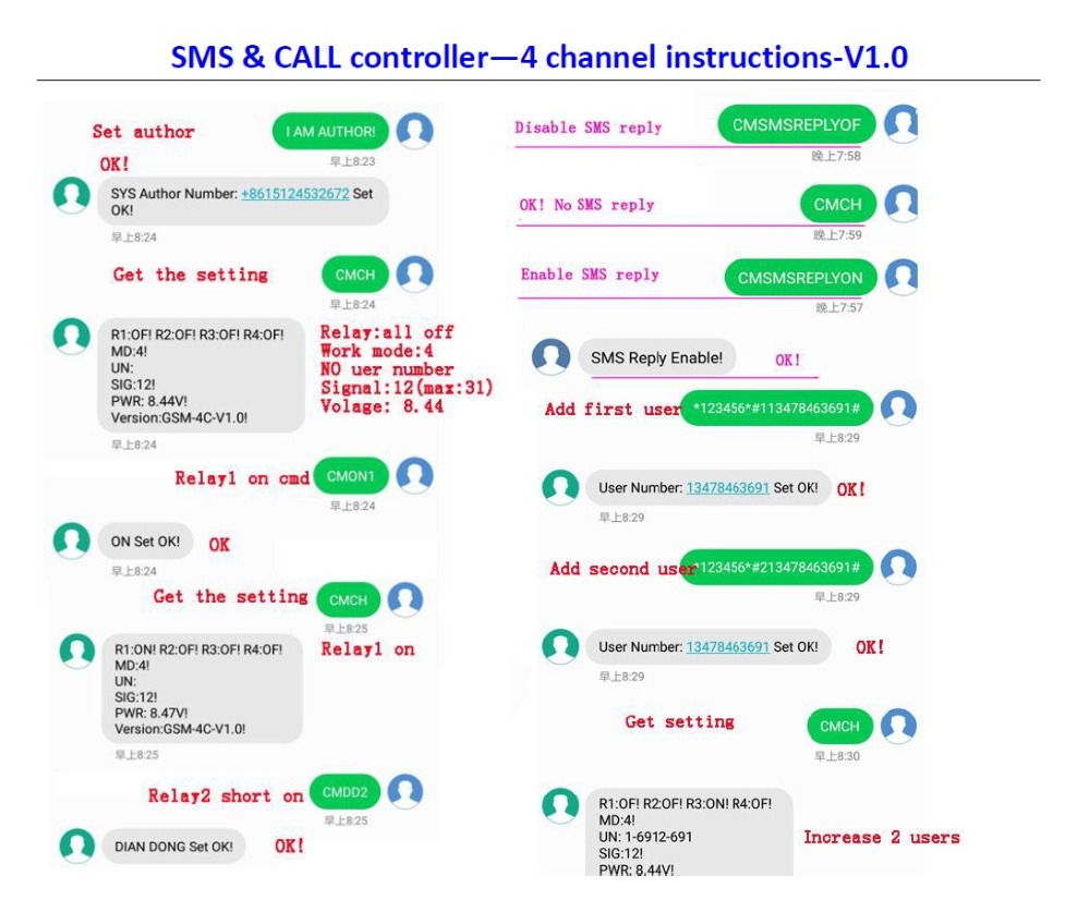
Administrator number configuration: Send, after setup successfully, the device will reply: Sys Author Number: ***Set OK. Administrator can only be set up if there is no administrator in the device. Note that the administrator number must be set firstly.
User number configuration: Command format:*code*#NUser number#, after setup successfully, the device will reply, SMS Content is: User Number: *** Set ok. For example, if system code is 123456, and you want to set the first authorized number 8846919911, you can send the SMS:*123456*#18846919911#.the device will reply: User Number: 8846919911 Set OK. The new user number is saved in the device. Description: the device supports up to 9 user numbers. Anyone who knows the code can replace or increase the user number. N is to set any user number, for example, when N is 1, it is the first user number, if you want to replace the 1 user number, the N in the command is 1; if you want to add the second user number, the N is 2; if you want to add the user number of 9, N is 9. Note that the user number is not necessarily to be set.
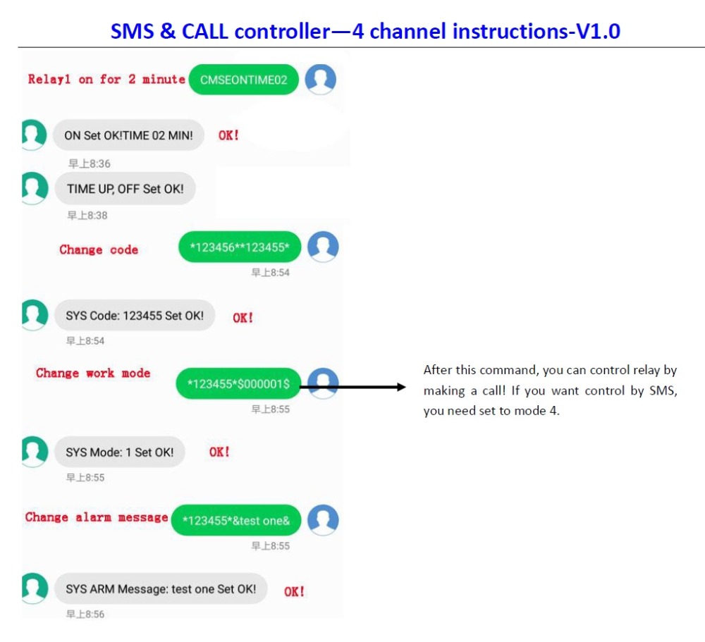
Code configuration: Format: *6 old code number**6 new code number*. After setup successfully, the device will reply: SYS Code: *** set ok. For example, if system code is 123456, you want to change the new code is 666666, send the SMS:*123456**666666*. The device will reply: SYS Code: 666666 Set OK. Note that only authorized number can change the code.
The SMS content of Switch quantity detection: Format: *6 code number*&content&. The maximum length of the content is 11 bytes. After setup successfully, the device will reply: SYS Arm Message: *** set ok. For example, if you want to change the new content is the first! Send the SMS:*123456*&the first!&. The device will reply: SYS Arm Message: the first! Set OK. Note that only authorized number can change the code.
Mode configuration: Format: *code*$00000N $, N=1, 2, 3, 4. If you want to set system work at mode 1, send the SMS: *123456*$000001$. The device will reply SYS Mode: 1 Set OK! Note that only authorized number can change the code.
SMS instruction reply or not: Send CMSMSREPLYON to enable the reply of SMS command, and CMSMSREPLYOF to disable the reply of SMS command. When enable the reply of SMS command successfully, device will reply: SMS Reply Enable! Note that only authorized number can change the code.
Delete User number command: Send CMDELETUSERN, (N=1-9).After setup successfully, the device will reply, SMS Content is: Delete User OK. If you want to delete the first user number, send CMDELETUSER1. Note that only authorized number can change the code.
Back to factory setting: Send CMGOTOFACTORYSET, after setup successfully, the device will reply: SYS Init OK! Note that only authorized number can change the code. This system has four work modes, the mode 1, mode 2 and mode 3 is using call to control the relay, and the Mode 4 is using SMS to control.
The following are the four work mode instruction:
Mode 1: The cell phone calls control. When the relay1 is in the off state, user make a call to the device, when this call connects, user can hear 3 ring of the bell, and then the call will be automatically hung up, and the relay1 will be in on. When the relay1 is in a state of on, user makes a call to the controller. When this call connects, you can hear 2 ring of the bell, and then the call will be automatically hung up, and the relay1 will be in the state of off. This control mode, the state of the relay1 will be saved.
Mode 2: The cell phone calls control. User makes a call to the controller with the authorized phone. When the device receives this call the relay1 will be in the state of on. When this call is disconnected, the relay1 will be in the state of off. This control mode, the state of the relay1 will not be saved.
Mode 3: The cell phone calls control. User makes a call to the controller with the authorized phone. When the device receives this call the relay1 will be in the state of on for 1-2 second, and then the relay1 will be in the state of off, and the call will be automatically hung up. This control mode, the state of the relay1 will not be saved.
Mode 4: OK
The cell phone SMS control.
Relay On command: CMONN, after successful setup, the device will reply SMS is: ON Set OK! For example, send the SMS: CMON1. Relay1 will be on; Send the SMS: CMON2. Relay2 will be on. Relay status will be saved.
All relay on command: CMONA, after successful setup, the device will reply SMS is: ON Set OK! Relays status will be saved.
Relay Off command: CMOFNN, after successful setup, the SMS Content is: OFF Set OK! Send the SMS: CMOF1. Relay1 will be off. Relay status will be saved.
All relay off command: CMOFA, after successful setup, the device will reply SMS is: OFF Set OK! Relays status will be saved.
Relay on for only 1-2 second command: CMDDN, after successful setup, the device will reply: Dian Dong Set OK! For example, send the SMS: CMDD1. Relay status will not be saved.
Relay1 on for 1-99 minute command: CMSEONTIME (2 bit times), after successful setup, the device will reply, SMS Content is: ON Set OK! TIME ** MIN! The timing range is 1-99 minutes. If you want to control Relay On for 1 minute, send the SMS: CMSEONTIME01. Relay status will not be saved. This command can only control relay1.
System status query instruction: CMCH. For example, sends the SMS: CMCH. Author and user can know the setting of the device. If you are the author, you will get the following information: status of relay, relay timer, work mode, three bit user number of in the later, signal of GSM module, the voltage of power, and the version of device; If you are the user, you will get the following information: status of relay, relay timer, work mode, and version of device.
Start to Use:
1. Insert a SIM card, Connect the antenna and power.
2. Wait until system is in the status of ldquoReady, can receive configure SMSrdquo, then send SMS command to set the author number, and then wait until system in the status of ldquoReady, can receive control relay SMSrdquo according to the LED indicator.
3. You can send SMS command or make a call to control relay.
Default Set:
SMS instruction reply or not: reply
Relays status: ALL off
Mode: 4
Code: 123456
Content of Switch quantity detection: 123456
Relay Connection Instructions:
The 4 relays in the device like switches, and the relay outputs are 3 pins, namely the common(COM), normally closed(NC) and normally open(NO). When relay is in on status, the result is that the common and the normally open are connected, and the common and normally closed are broken. When relay is in off status, the result is that the common and the normally open contact are disconnected, and the common and the normally closed contact are connected.
In practical applications, we only need to connect two terminals, and the common pin must be connected, and either normally open pin or normally closed pin must be connected. When the equipment is power off, the common pin of the relay must be connected with normally closed pin.
EASY COMMAND