| Quantity | 3+ units | 10+ units | 30+ units | 50+ units | More |
|---|---|---|---|---|---|
| Price /Unit | $63.99 | $62.69 | $60.73 | $58.12 | Contact US |
 CM600 6-Axis CNC Motion Controller Board DC24V 24 Inputs and 18 Outputs with Display for CNC 3D Real-time Motion Tracking
$956.76
 CM400 4-Axis CNC Motion Controller Board DC24V 16 Inputs and 12 Outputs with Display for CNC 3D Real-time Motion Tracking
$490.36
 CM300 3-Axis CNC Motion Controller Board DC24V 12 Inputs and 8 Outputs with Display for CNC 3D Real-time Motion Tracking
$373.77
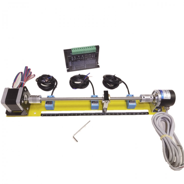
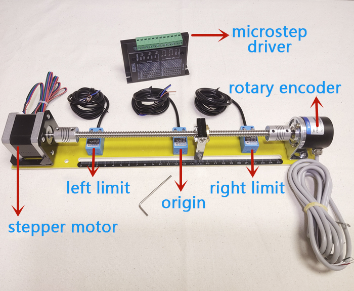
Sliding Table Kit Stepper Motor Learning Positioning Control Stroke 9.8" w/ Encoder Microstep Driver
Read Before Purchasing:
- Default NPN. NPN and PNP are optional. If you need PNP, please contact us.
- Use the stepping screw to learn positioning function, which must be combined with PLC action. Without PLC, the action cannot be completed (a certain PLC programming knowledge is required).
- The PLC must come with a transistor output (such as for Mitsubishi-MT and Siemens-DC/DC/DC), which can send pulses to control the stepper motor, but relays cannot control the stepper motor.
- We only provide related wiring diagrams (electronic files) for Mitsubishi FX, Siemens 200, 200SMART, and 1200. Please finish basic operations by yourselves.
Features:
- Total length 385mm/15.2", stroke 250mm/9.8", width 50mm/2", height 60mm/2.4"
- Brand new 42 stepper motor. Two-phase four-wire system, 1.5A, 1.8°, and 0.3N.m. High-speed response, high efficiency and precision, uniform speed, and stable performance
- Photoelectric incremental rotary encoder. 600 pulses, AB two-phase, imported components, high-speed bearings, pulse stability (PNP, NPN can be selected at will)
- Metal induction switch, with sensing distance 1mm/0.04"
- Microstep driver control signal. 3.3V-24V universal. Requiring no resistor in series
Specifications:
- Total length 385mm/15.2", stroke 250mm/9.8" (the length cannot be customized)
- Encoder type: photoelectric incremental AB two-phase 600 pulse. Default NPN (NPN and PNP are optional. If you need PNP, please contact us)
- Encoder wiring: red wire to 24V+, black wire to 0V and negative pole, white wire to pulse A, and green to pulse B
- Sensor type: Three-wired. The default is NPN normally closed (NPN and PNP are optional. If you need PNP, please contact us)
- Sensor wiring: brown wire to 24V+, blue wire to 0V and negative pole, and black (signal output)
- Stepping motor current: 1.2-1.5A, step angle 1.8°, 200 pulses/turn (the number of pulses can be adjusted)
- Stepper motor wiring: red wire to A+, blue wire to A-, green to B+, and black to B-
- Screw pitch of sliding table: 2mm/0.08" per circle
- Driver description: pulse direction enable port does not require resistor in series
Precautions:
1. The motor current is set strictly in accordance with the given parameters and corresponds to the current set by the driver. The maximum speed of the stepping motor is 600 rpm. The first commissioning, the number of pulses should not exceed the maximum speed of the motor after calculation.
2. Regarding the limit sensor (proximity type). NPN type sensor outputs low level signal when sensing, PNP type sensor outputs high level signal when sensing. When PLC for Siemens uses NPN type sensor and encoder, the common end (1M) of the input point is connected to 24V+. When using PNP type sensors and encoders, the common terminal (1M) of the input point is connected to 0V and negative pole.
Package Included:
- 1 x Set of Sliding Table
Note:
- Please not connect to 220V power supply.
- It is recommended to debug the DIP switch without power on.
Common Faults, Causes & Solutions:
1. Alarm indicator is off:
Reason A: Wiring error of motor (please check and wire again)
Reason B: The voltage is too large or too small (please check your power supply)
2. The motor does not work and there is no holding torque:
Reason A: Wiring error of motor (rewire the motor)
Reason B: Offline enable RESET signal is valid (make RESET invalid)
3. The motor does not work and has a holding torque:
Reason A: No pulse signal input (adjust pulse width and signal level)
Reason B: The subdivision is too small (choose a correct subdivision)
Reason C: The current setting is too small (select a correct current)
Reason D: The driver has been protected (repowered after power failure)
4. Wrong direction of motor rotation:
Reason A: The phase sequence of the power line is connected incorrectly (Exchange any two connected lines. For example, reconnect A+ and A-)
Reason B: There is an open circuit in the motor wire (check and rewire)
Reason C: The direction signal input is incorrect (change the direction setting)
5. Motor torque is too small:
Reason A: The phase current is set too small (set a correct phase current)
Reason B: Acceleration is too fast (decrease acceleration)
Reason C: Motor blocked (mechanical troubleshooting)
Reason D: The driver does not match the motor (change a suitable driver)
6. Inaccurate location:
Reason A: The signal is interfered (remove the interference)
Reason B: Subdivision error (set a correct subdivision)
Reason C: The current is too small (increase the current)
Reason D: Bad connection of motor wire (check and connect correctly)
7. Motor acceleration blocked:
Reason A: The acceleration time is too short (prolong the acceleration time)
Reason B: Motor torque is too small (choose a suitable torque motor)
Reason C: Voltage or current is too low (increase the voltage or increase the current)