| Quantity | 3+ units | 10+ units | 30+ units | 50+ units | More |
|---|---|---|---|---|---|
| Price /Unit | $173.48 | $169.94 | $164.63 | $157.55 | Contact US |
 AD9379-A RF Evaluation Board Dual RF RX/TX Replacement for ADRV9009 Transceiver RF Board
$833.04
 USB/MIDI Dual-mode Computer Volume Adjuster Music Play Controller Compatible with Windows/Mac Systems
$81.65
 BU-5 Bluetooth Module Radio Bluetooth Adapter Unit for Yaesu FTM-150R FTM-510DR Transceiver
$55.79
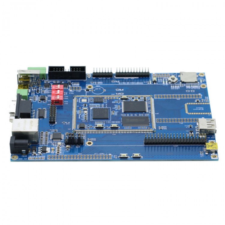
STM32F767NI Development Board ARM 32bit Cortex Support MJPEG Video for Arduino
Processor parameters:
- Core: ARM 32-bit Cortex -M7 CPU with DPFPU, ART Accelerator™ and L1-cache: 16 Kbytes I/D cache, allowing 0-wait state execution from embedded Flash and external memories, up to 216 MHz, MPU, 462 DMIPS/2.14 DMIPS/MHz (Dhrystone 2.1), and DSP instructions.
- Up to 2 Mbytes of Flash memory organized into two banks allowing read-while-write
- SRAM: 512 Kbytes (including 128 Kbytes of data TCM RAM for critical real-time data) + 16 Kbytes of instruction TCM RAM (for critical real-time routines) + 4 Kbytes of backup SRAM
- Flexible external memory controller with up to 32-bit data bus: SRAM, PSRAM, SDRAM/LPSDR SDRAM, NOR/NAND memories
- Dual mode Quad-SPI
- Graphics
- Chrom-ART Accelerator™ (DMA2D), graphical hardware accelerator enabling enhanced graphical user interface
- Hardware JPEG codec
- LCD-TFT controller supporting up to XGA resolution
- MIPI® DSI host controller supporting up to 720p 30 Hz resolution
- Clock, reset and supply management
- 1.7 V to 3.6 V application supply and I/Os
- POR, PDR, PVD and BOR
- Dedicated USB power
- 4-to-26 MHz crystal oscillator
- Internal 16 MHz factory-trimmed RC (1% accuracy)
- 32 kHz oscillator for RTC with calibration
- Internal 32 kHz RC with calibration
- Low-power
- Sleep, Stop and Standby modes
- VBAT supply for RTC, 32×32 bit backup registers + 4 Kbytes backup SRAM
- 3×12-bit, 2.4 MSPS ADC: up to 24 channels
- Digital filters for sigma delta modulator (DFSDM), 8 channels / 4 filters
- 2×12-bit D/A converters
- General-purpose DMA: 16-stream DMA controller with FIFOs and burst support
- Up to 18 timers: up to thirteen 16-bit (1x low- power 16-bit timer available in Stop mode) and two 32-bit timers, each with up to 4 IC/OC/PWM or pulse counter and quadrature (incremental) encoder input. All 15 timers running up to 216 MHz. 2x watchdogs, SysTick timer
Debug mode
- SWD & JTAG interfaces
- Cortex®-M7 Trace Macrocell™
- Up to 168 I/O ports with interrupt capability
- Up to 164 fast I/Os up to 108 MHz
- Up to 166 5 V-tolerant I/Os
- Up to 28 communication interfaces
- Up to 4 I2 C interfaces (SMBus/PMBus)
- Up to 4 USARTs/4 UARTs (12.5 Mbit/s, ISO7816 interface, LIN, IrDA, modem control)
- Up to 6 SPIs (up to 54 Mbit/s), 3 with muxed simplex I2 S for audio
- 2 x SAIs (serial audio interface)
- 3 × CANs (2.0B Active) and 2x SDMMCs
- SPDIFRX interface
- HDMI-CEC
- MDIO slave interface
- Advanced connectivity
- USB 2.0 full-speed device/host/OTG controller with on-chip PHY
- USB 2.0 high-speed/full-speed device/host/OTG controller with dedicated DMA, on-chip full-speed PHY and ULPI
- 10/100 Ethernet MAC with dedicated DMA: supports IEEE 1588v2 hardware, MII/RMII
- 8- to 14-bit camera interface up to 54 Mbyte/s
- True random number generator
- CRC calculation unit
- RTC: subsecond accuracy, hardware calendar
- 96-bit unique ID
Hardware configuration for the development board:
- Industrial device
- 256M Bit SDRAM (32 bit data width)
- 256M Bit QSPI NOR Flash
- 1M Bit IIC EEPROM
- Reserved for a WSON8 package SPI Flash, optional NOR (maximum 512M Bit) or NAND (maximum 4G Bit) SPI Flash
- 20 pin 2.54 pitch JTAG interface
- 10/100M Ethernet interface (MII, RMII two configuration mode, physical layer chip DP83848)
- Two USB2.0 full speed master slave device interfaces
- Two USB2.0 full speed master interfaces
- A USB2.0 high speed interface (need to add high-speed USB physical layer module)
- One channel RS232 interface
- One channel RS485 interface
- Two channel CAN2.0 interface
- Bluetooth module ELET114A interface
- Reserved Zigbee module ZM5168P0-1 interface
- Reserved Wi-Fi module USR-WIFI232 interface
- Micro SD memory card slot (SDIO 4-bit)
- The DCMI interface of 8 bit and 12 bit data width (row contains the IIC pin)
- Multipurpose audio interface, can be connected with common RF module (pin empty posts)
- A SPI interface, can be connected with common RF module (pin empty posts)
- 32 bit bus extension interface (address line to A12)
- RGB888 LCD interface
- 1* controllable LED
- A five way navigation key
- A key with wake up function
- An adjustable resistor
- Reserved for RTC power supply 0.33F capacitor location (does not weld the capacitor yet)
Package Contents:
- 1 x MiniSTM32F767NI development board
- 1 x RGB888 converter baord
- 1 x Power supply
- 1 x USB cable
- Cables