| Quantity | 3+ units | 10+ units | 30+ units | 50+ units | More |
|---|---|---|---|---|---|
| Price /Unit | $237.87 | $233.01 | $225.73 | $216.02 | Contact US |
V30 RF Power Meter USB Type-C with Spectrum Display 5MHz-13GHz Portable Handheld Spectrum Analyzer
Specification:
- Model: V30 power meter - 13GHz portable spectrum analyzer
- Frequency range: 5MHz - 13GHz
- Maximum scanning span: 6000MHz
- Measuring time: ≤100ms
- Bandwidth: 300kHz (fixed)
- Minimum frequency step: 20kHz
- Measuring frequency error: ±0.1MHz
- Background noise: < -80dBm
- Impedance: 50ohms
- Measuring power range (connect with external attenuator): +30dBm ~ -80dBm
- Maximum input power: +10dBm
- Measuring power error: ±0.5dB
- Communication interface: USB Type-C, TTL serial port
- Upper computer: support
- Battery: 3500mA
- Product size: 97 x 50 x 30mm
- Net weight: 273g
Package Included:
- 1 x RF Power Meter
- 1 x Type-C Cable
Vice-computer Operation Instruction:
- Button function description:
1. "▲": Press and hold to save data/short press to increase value.
2. "▼": Short press to decrease the value.
3. ”◀”: Short press the cursor to left/left to select the data type.
4. ”▶”: Short press the cursor to the right/right to select the data type.
5. "OK": Press and hold to turn off/Short press to turn on/Short press to select the current value for modification in power on mode, then short press again to confirm.
Vice-computer Functional Description:
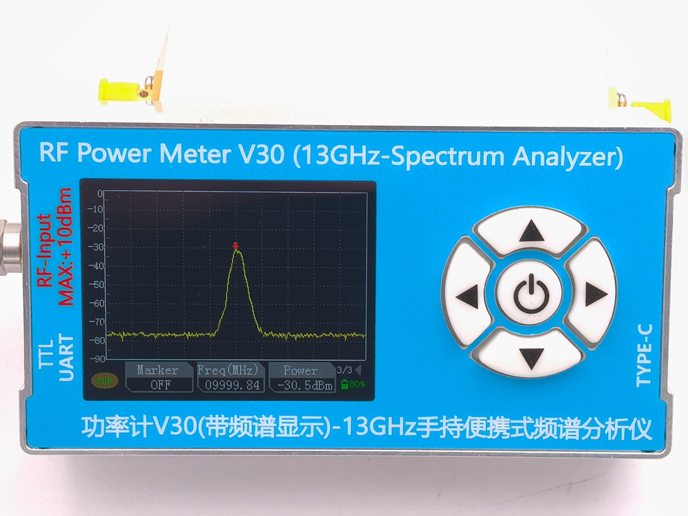
First Page Menu:
- Center: Represents the center frequency, with an input range of 1MHz-13000MHz.
- SPAN: Indicates scanning bandwidth, input range 6MHz-6000MHz.
- RBW: Indicates the scanning step frequency, with an input range of 20KHz-20000KHz.
- Note: The setting of each parameter is not independent, and the three parameters are interrelated.
Second Page Menu:
- OFFSET: Indicates the power error calibration value.
- AMPT: Indicates the external attenuation value.
- MODE: Press the up button to switch to the upper computer mode/press the down button to switch to the vice computer mode.
- Note: When set to the upper computer mode, the display of the vice computer pauses.
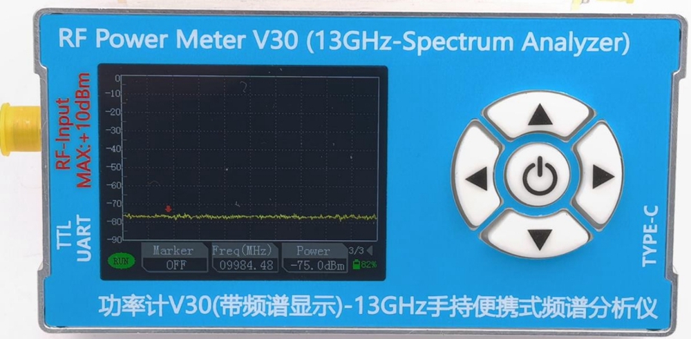
Third Page Menu:
- Marker: Select to turn on the cursor, press the up button to turn on cursor mode/press the down button to turn off cursor mode, and when turning on cursor mode, the left and right arrow keys can only move the cursor.
- Freq (MHz): Indicates the frequency value of the maximum frequency point signal measured within the current frequency band.
- Power: Indicates the maximum power value within the currently measured frequency band.
Upper Computer Operation Instruction:
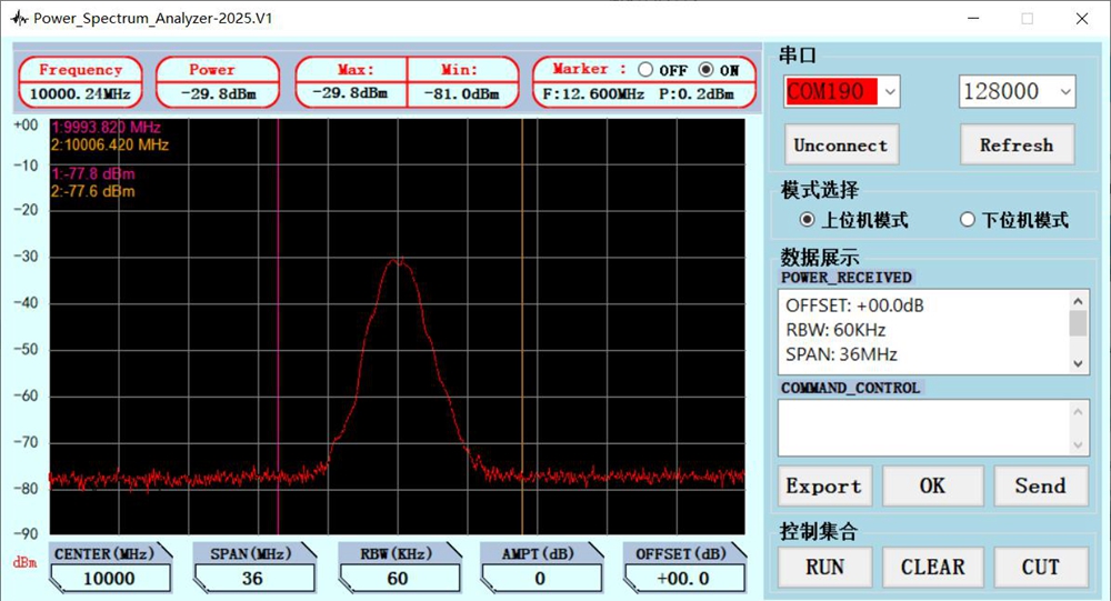
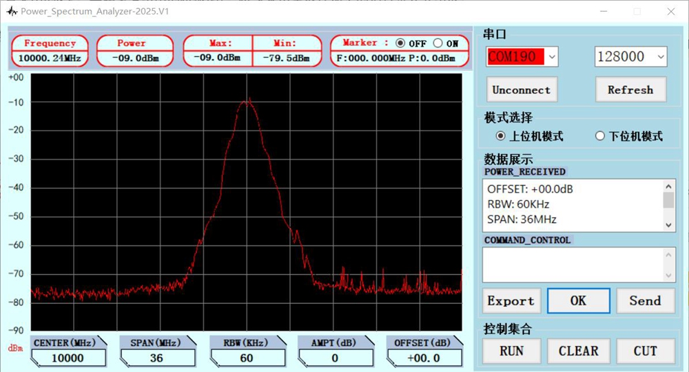
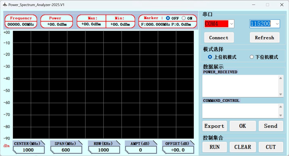
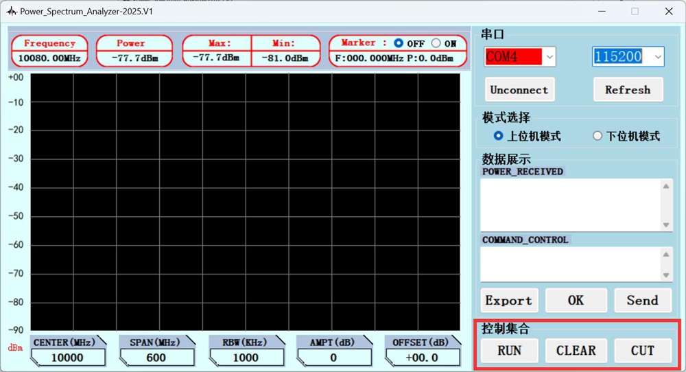
- Overall diagram of Power_Spectrum_Analyzer on the upper computer:
- Instructions:
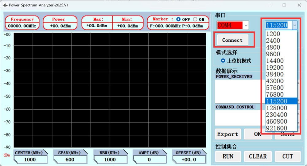
1. Power on connection:
After opening the upper computer program, first click the Refresh button to refresh and find the corresponding serial port number, and then click the Connect button to connect.
2. Mode selection:
Click to select the upper computer mode/vice computer mode.
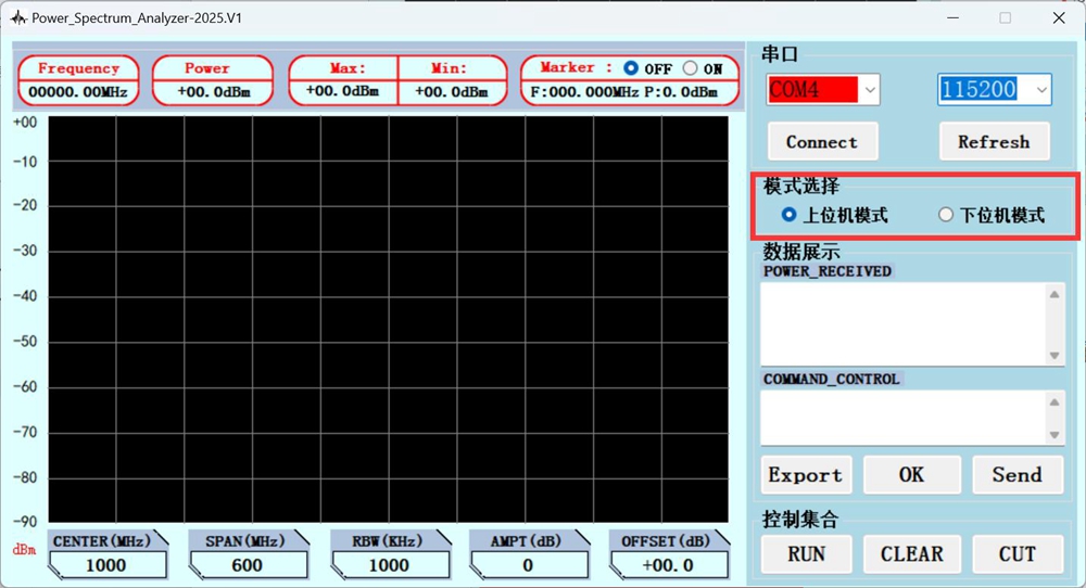
When selecting the upper computer mode, the display of vice computer data and spectral lines is paused and controlled and displayed by the upper computer.
3. Data display
* POWER_RECEIVED: After the parameter settings are issued for the data receiving box, the data returned by the vice computer can be viewed here.
* COMMAND_CONTROL: Send command window, mainly used for command control in vice computer mode.
* Export: Export the current data to the ExportData folder.
* OK: In the upper computer mode, send the parameter setting column under the spectral line window bar to the vice computer uniformly.
* Send: In the vice computer mode, send the control instructions in the COMMAND_CONTROL to the vice computer.
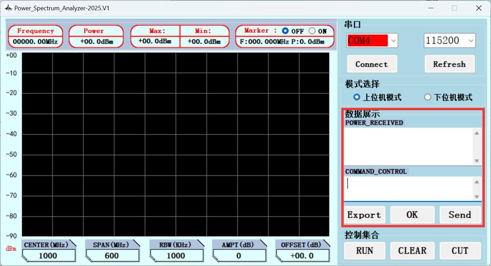
4. Control set:
* RUN: Indicates that the current waveform is running. Click and switch to STOP to stop the waveform and pause the current frame waveform for viewing.
* CLEAR: Click to clear all current data and re measure.
* CUT: Take a screenshot of the current page to the current folder directory on the upper computer.
Data display interface:
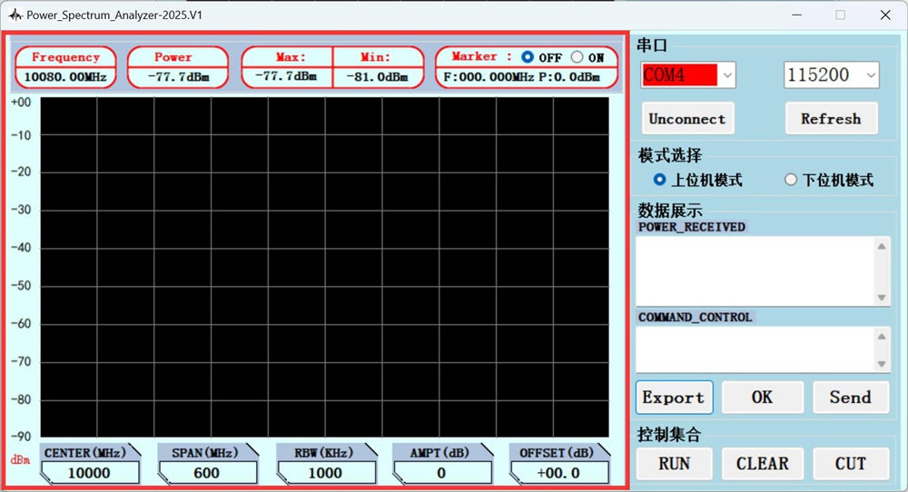
Parameter display bar: used for displaying data collected in the upper computer mode.
* Frequency: Indicate the current measured frequency.
* Power: Indicates the current measured power.
* Max: Indicate the maximum power value.
* Min: represents the minimum power value.
* Marker: Click ON to turn on cursor mode, click OFF to turn off. F represents the frequency difference between the two current cursor modes, and P represents the power difference between the two current cursor modes.
Parameter setting column: used for setting the upper computer mode.
* CENTER (MHz): Select and set the current center frequency.
* SPAN (MHz): Select and set the current scanning bandwidth.
* RBW (kHz): Select and set the current scanning bandwidth step frequency.
* AMPT (dB): External access attenuator value.
* OFFSET (dB): Power error calibration value.
Serial Communication Protocol - Vice Computer Mode Control
- Communication method:
1. USB Type-C communication, no need to set baud rate.
2. TTL serial communication, set the baud rate to 128000.
- In the upper computer software, click on the vice computer mode, enter the control command character in COMMAND_CONTROL, and click Send to send; Or use the serial assistant to send the corresponding control command characters.

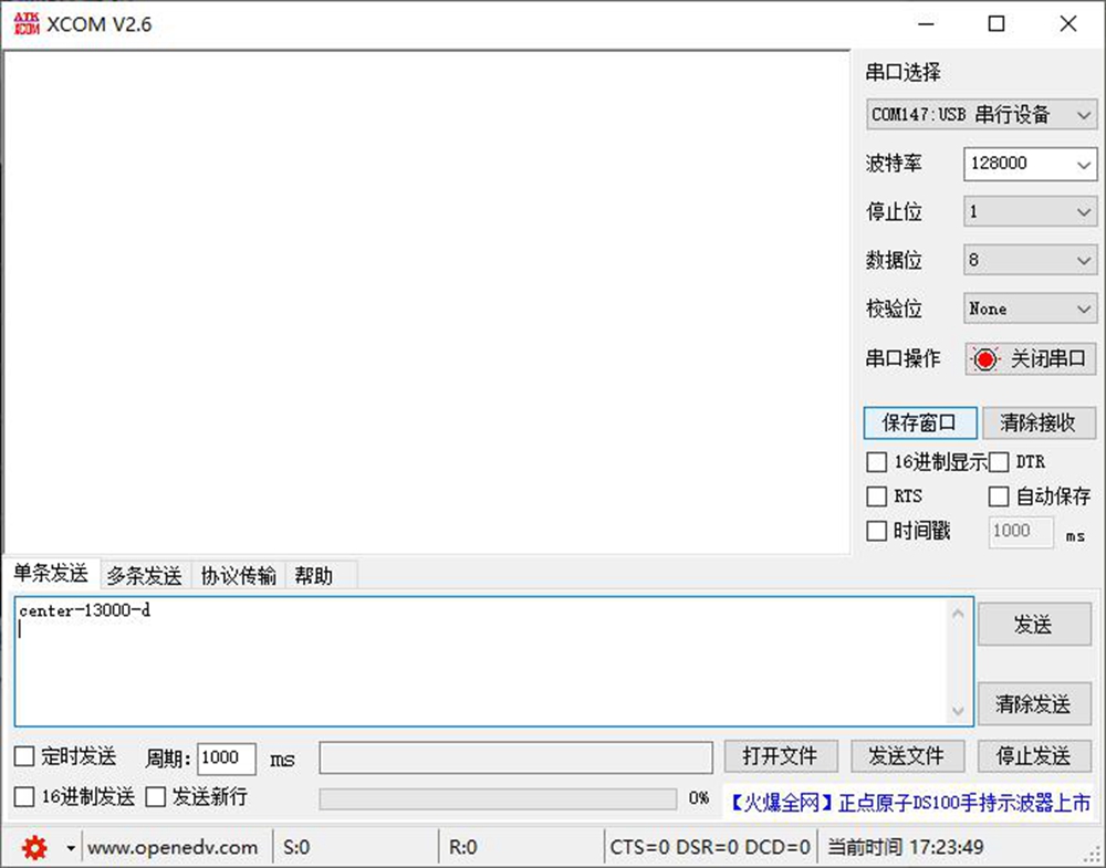
- Data Writing:
1. Set the center frequency: for example, set the center frequency to 3000MHz.
center-03000-d
Received: “Set center frequency to 3000” indicates successful setup.
2. Set SPAN bandwidth: for example, set the scanning bandwidth to 600MHz.
span-0600-d
Received: “Set SPAN bandwidth to 600” indicates successful setting.
3. Set RBW bandwidth: for example, set the scanning step to 1000KHz.
rbw-01000-d
Received: 'Set RBW bandwidth to 1000' indicates successful setting.
4. Set OFFSET: for example, set the power calibration to +1.0dB or -1.0dB.
offset+/-01.0-d
Received: "Set OFFSET to +1.0" or "Set OFFSET to -1.0" indicates successful setting.
5. Set AMPT: set the external access attenuator value to 30dB.
ampt-30-d
Received: “Set AMPT bandwidth to 30” indicates successful setting.
6. Serial control together: set all parameters at once.
com-01000-0300-01000-00.0-00-d
Or:
com-01000-0300-01000+00.0-00-d
Received: "Serial settings: center 1000MHz, span 300MHz, rbw 1000KHz, offset +0.0dB, ampt 0dB" or "Serial settings: center 1000MHz, span 300MHz, rbw 1000KHz, offset -0.0dB, ampt 0dB" indicates successful setting.
- Data Reading:
1. Read the current set parameter values: Read-ALL+PSA.
2. Read the maximum pulse power value within the current frequency band: Read-PPS+PSA.
3. Continuous transmission of power value data: PSA-Power (sending frame header a, frame footer A, one frame of 300 data).
4. Pause continuous transmission of power value data: PSA-STOP.
5. Store the currently set data: PSA-SAVE.
Waveform Data Chart:
- Vice computer display: Taking 10GHz test signal as an example