| Quantity | 3+ units | 10+ units | 30+ units | 50+ units | More |
|---|---|---|---|---|---|
| Price /Unit | $6.82 | $6.68 | $6.47 | $6.19 | Contact US |
 AD9379-A RF Evaluation Board Dual RF RX/TX Replacement for ADRV9009 Transceiver RF Board
$833.04
 USB/MIDI Dual-mode Computer Volume Adjuster Music Play Controller Compatible with Windows/Mac Systems
$81.65
 BU-5 Bluetooth Module Radio Bluetooth Adapter Unit for Yaesu FTM-150R FTM-510DR Transceiver
$55.79
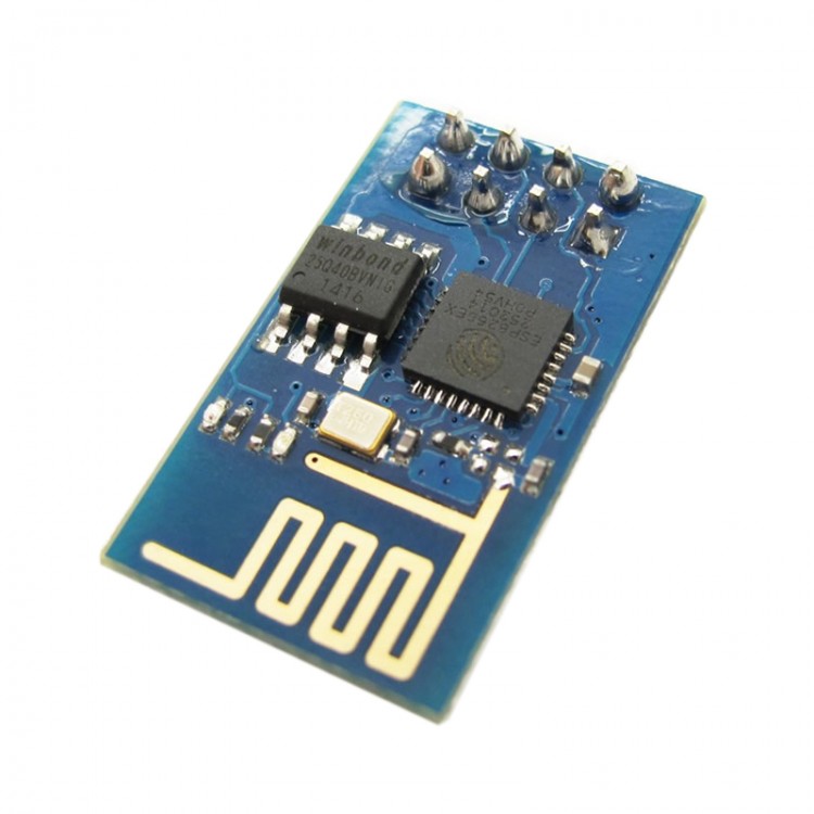
Wee Serial WIFI Module ESP8266 Seriel Port WIFI Module Wireless Control for Arduino
Description:
Wee is a WIFI module based on ESP8266 SoC. ESP8266 comes out of nowhere and has been taking by storm the IoT world. You can find many hacking projects about it on the internet. So far, the most popular ESP8266 breakout version only has GPIO0 and GPIO2 routed to the header. Compared to it, Wee WIFI module is designed with a standard Bee interface and has more GPIOs available for developers. In a word, users can take full use of the utility of ESP8266 SoC by using Wee WIFI module in your projects.
Features:
- Standard Bee interface
- indicators: TX, RX, PWR
- FW/Work Switch
- More GPIOs help developer take full use of the utility of ESP8266 SoC
Specification:
PCB Size: 23.9X26.2X1.6mm
Interface: Bee interface
Indicators: PWR, TX, RX
Note:
- Work/FW Switch
When program firmware into ESP8266, you should ensure the switch is in FW mode.
For the normal usage of this module, you should ensure the switch is in work mode.
Note:
- Firmware enable pin
When set to 0, power or reset the wee module, you can access to the firmware uploading mode;
When set to 1, power or reset the wee module, you can access to the normal work mode
Instruction:
ESP8266 base: Click here
Open the uartWIFI.h file, because the Mini RBoard uses the same chip as UNO, so remove the definition of UNO file in the H notes, write off MEGA.
#define UNO
//#define MEGA
Then define_DBG_RXPIN_and_DBG_TXPIN_pins as D9 and D10.
#define _DBG_RXPIN_ 9 //A0
#define _DBG_TXPIN_ 10 //A1
reserve uartWIFI.h file.
Progrem the code: plug into the FOCA
#define SSID "Itead_1(Public)"//type your own SSID name
#define PASSWORD "27955416"0//type your own WIFI password
#include "uartWIFI.h"
#include <SoftwareSerial.h>
WIFI wifi;
extern int chlID;//client id(0-4)
void setup()
{
pinMode(4,OUTPUT);
pinMode(5,OUTPUT);
pinMode(6,OUTPUT);
pinMode(7,OUTPUT);
wifi.begin();
bool b = wifi.Initialize(STA, SSID, PASSWORD);
if(!b)
{
DebugSerial.println("Init error");
}
delay(8000); //make sure the module can have enough time to get an IP address
String ipstring = wifi.showIP();
DebugSerial.println(ipstring);//show the ip address of module
delay(2000);
wifi.confMux(1);
delay(100);
if(wifi.confServer(1,8080))
DebugSerial.println("Server is set up");
}
void loop()
{
char buf[100];
int iLen = wifi.ReceiveMessage(buf);
if(iLen > 0)
{
//mini Rboard'relay is D4 pin
if (strcmp(buf, "CH0ON") == 0)
{
digitalWrite(4,HIGH);
DebugSerial.println("CH0ON");
}
if (strcmp(buf, "CH0OFF") == 0)
{
digitalWrite(4,LOW);
DebugSerial.println("CH0OFF");
}
/* The following 3 channels can be used for 4chanels Rboard D5 D6 D7
if (strcmp(buf, "CH1ON") == 0)
{
digitalWrite(5,HIGH);
DebugSerial.println("CH1ON");
}
if (strcmp(buf, "CH1OFF") == 0)
{
digitalWrite(5,LOW);
DebugSerial.println("CH1OFF");
}
if (strcmp(buf, "CH2ON") == 0)
{
digitalWrite(6,HIGH);
DebugSerial.println("CH2ON");
}
if (strcmp(buf, "CH2OFF") == 0)
{
digitalWrite(6,LOW);
DebugSerial.println("CH2OFF");
}
if (strcmp(buf, "CH3ON") == 0)
{
digitalWrite(7,HIGH);
DebugSerial.println("CH3ON");
}
if (strcmp(buf, "CH3OFF") == 0)
{
digitalWrite(7,LOW);
DebugSerial.println("CH3OFF");
}
*/
}
}
stick the code to the arduino IDE, and revise the name of WIFI and password in the SSID and PASSWORD.
#define SSID "Itead_1(Public)" //type your own SSID name
#define PASSWORD "27955416" //type your own WIFI password
Package included:
- 1 x WIFI Module