| Quantity | 3+ units | 10+ units | 30+ units | 50+ units | More |
|---|---|---|---|---|---|
| Price /Unit | $202.66 | $198.53 | $192.32 | $184.05 | Contact US |
 GCDQCN 4P 100A ATS Automatic Transfer Switch (4P100A) for 35mm Rail and Lighting Distribution Box
$40.16
GCDQCN 4P 100A ATS Automatic Transfer Switch (4P100A) for 35mm Rail and Lighting Distribution Box
$40.16
 GCDQCN 2P 100A ATS Automatic Transfer Switch (2P100A) for 35mm Rail and Lighting Distribution Box
$33.33
GCDQCN 2P 100A ATS Automatic Transfer Switch (2P100A) for 35mm Rail and Lighting Distribution Box
$33.33
 AI-30 0.05μm Fourth Generation Trunk Line Optical Fiber Fusion Splicer Delay Return Electric One-step Fiber Cleaver
$1,060.08
AI-30 0.05μm Fourth Generation Trunk Line Optical Fiber Fusion Splicer Delay Return Electric One-step Fiber Cleaver
$1,060.08
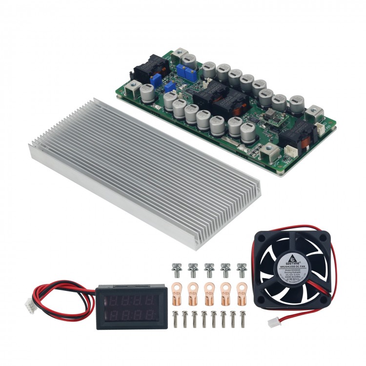
YF-BKT60V80A 12-48V/80A DC Automatic Buck Boost Converter Module Step up down Converter Full Set
Read before purchasing:
-
During charging, pay attention to the use of the corresponding range of
power adapters to avoid excessive current affecting the life of the
product and safety accidents.
- It is necessary to install the fixing
screws of the board and then install the screws of the positive and
negative terminals of the input and output, otherwise it may cause
damage to the upper plate by unsoldering. If similar situations occur,
the product will not be warranted.
- Basic technical knowledge and hands-on ability are highly recommended.
- Users need to modify parameters such as undervoltage protection parameters. We can tell you how to modify it.
-
Certain power supply test and measurement capabilities and equipment
are recommended. Do not test this power supply with a 3A adjustable
regulated power supply used in labs.
- Do not test the current-limiting power supply in CC mode of an electronic load.
-
Output current adjustment range: If the input power is sufficient, and
the output power supply is 20V and a 0.4Ω resistor is connected to
adjust CC potentiometer, the output current can be adjusted to a maximum
of 50A, but cannot be adjusted to the minimum limit value (except 0A).
Features:
- DC-DC step up down power supply with high current
- 4-way master-slave staggered parallel
- Good sharing current and adjustable voltage and current
- Can be directly paralleled to higher currents
- With over-temperature protection
Typical Performance (YF-BKT60V80A):
- Non-isolated four-switch synchronous buck-boost
- Wide input DC9-58V, output DC3-56V
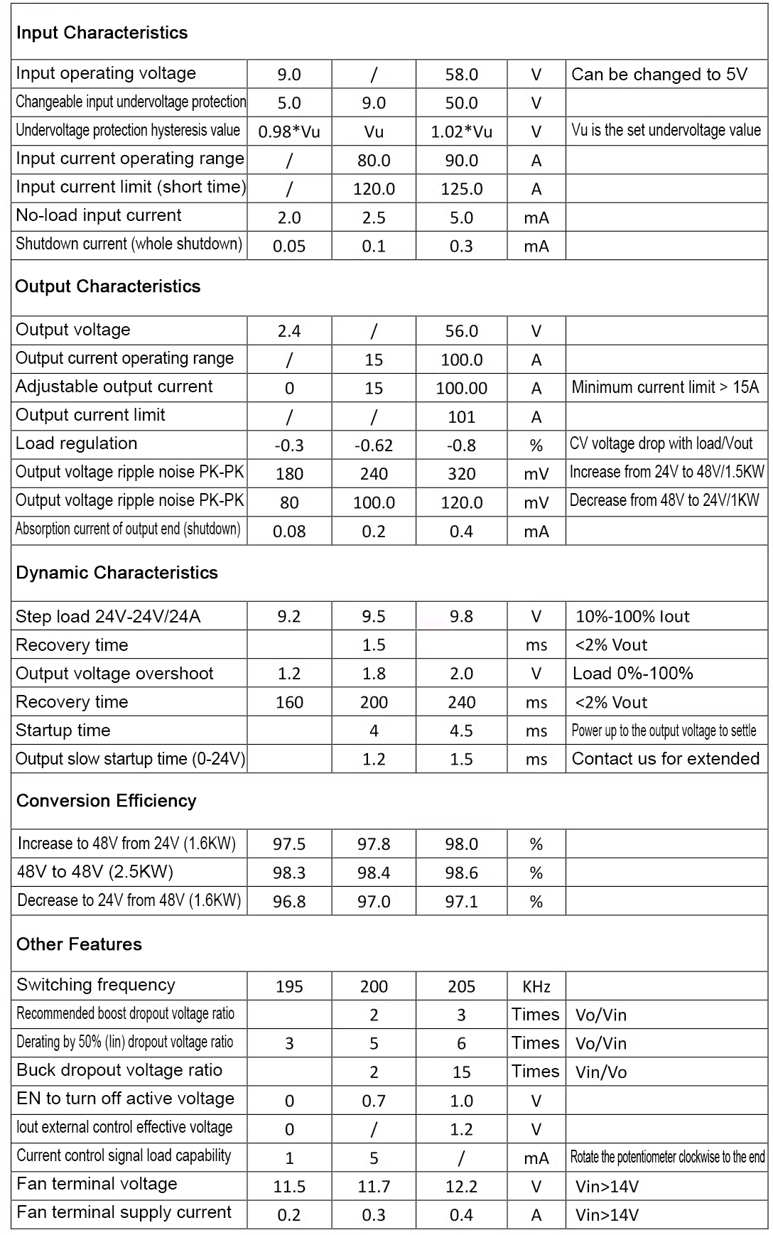
- Peak efficiency> 98.0%
- Over-current protection
- Short-circuit protection self-recovery
- Remote ON/OFF
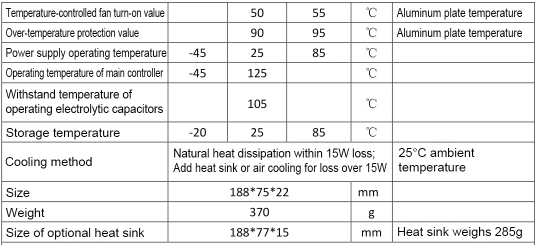
- Over-temperature protection
- Optional temperature-controlled fan
- Constant current indicator light
- Adjustable output voltage and current
- Output current is externally controllable
- Parallel connection can be easily expanded
- Battery charge back-charge protection up to 60V
- Super capacitor 0 voltage constant current charging
- Input voltage tracking regulation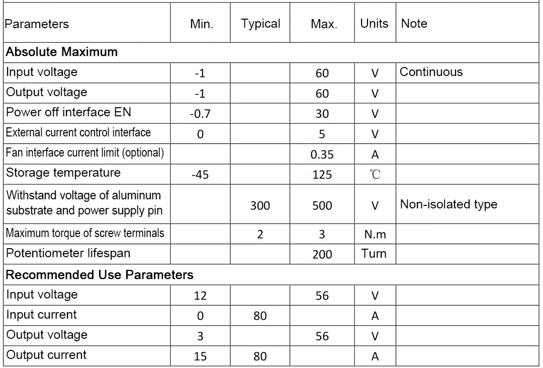
Attention:
1: Use sprayable conformal paint or potting for protection in humid environment.
2:
Can be directly connected to battery for charging. It is recommended to
adjust the output voltage correctly before connecting the target
battery.
3: Slow startup time and EN enable control delay time. When
the input source start-up time is long, the output slow startup time
needs to be adjusted. For example, the AC adaptation output full-load
voltage settling time is 50ms, while the power supply startup time is
2ms, which may cause AC to fail to start properly with load. You need to
start the AC power supply first, and then start the DC power supply.
4: For different applications, some parameters may need to be adjusted.
Package Included:
- 1 x Set of Buck Boost Converter (power supply board + auxiliary power board + digital display + heat sink)
Note:
- Battery is not included in the package.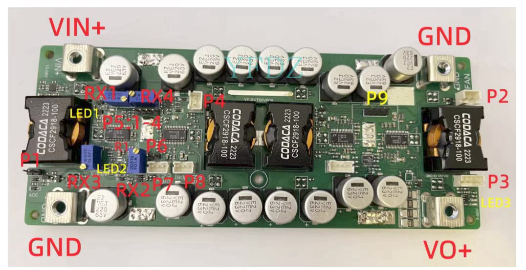
Attention:
1:
When testing this power supply, it must be ensured that the input
source can provide a large enough current (>120A) to ensure that the
power supply does not collapse or even be damaged when starting at full
load, especially when starting with load.
2: The startup time of the
input source must be less than the startup time of this power supply
(such as the adapter as input), otherwise it may not be possible to
start with load.
3: The input wire connected to this power supply
shall not be too long (the internal resistance of the wire shall not be
too large), otherwise the power supply may cause oscillation and
abnormality.
4: If there is a diode in series with the input source
to this power supply, the power supply may be damaged by the surge
voltage caused by the instantaneous on-off (line BOOST effect).
5: Do
not use the CC mode of an electronic load as the load of this power
supply. It is recommended to use the CR mode. CC mode draws current,
this power supply is current limited, and the constant current state
will cause this power supply to crash.
6: It is recommended to
connect the adjustable output voltage with a resistive load (dummy load)
with small current, to ensure real-time adjustment of the output
voltage potentiometer. Otherwise, the output voltage will change slowly
and the regulation will be inaccurate.
Parallel Connection: divided into master and slave
1:
Do not modify the master. The voltage and current after parallel
connection can only be adjusted by adjusting the potentiometer of the
host.
2: Rotate the RX1 potentiometer clockwise to the end, RX2 clockwise to the end, and RX3 counterclockwise to the end.
3: Remove the R1 resistor from the slave (623, to the left of the CC character).
4: Remove the P5 jumper cap of the slave and connect it to P6.
5: Connect the P7 interface of the host to the P8 interface with a cable.
6: The positive and negative poles of the input and output are connected together.
7: The above operations must be completed before powering on.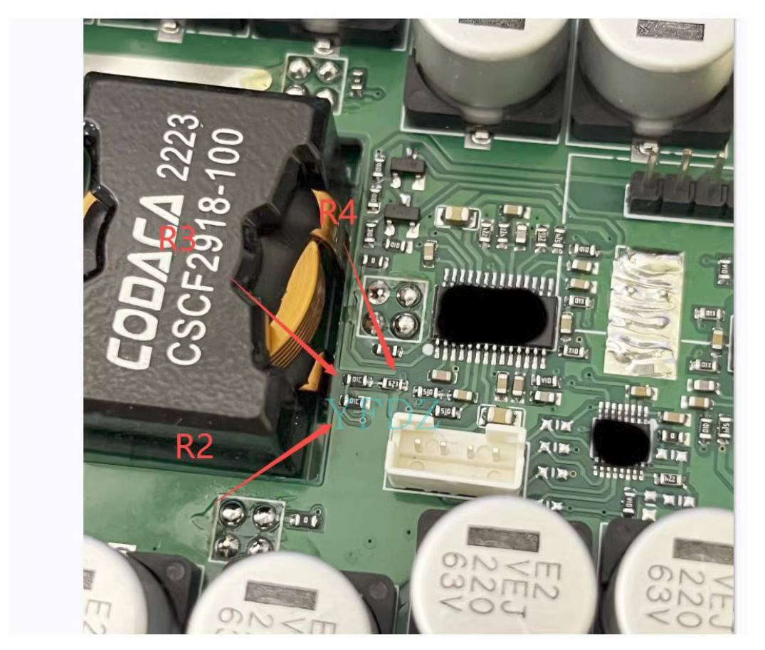
Modify Undervoltage Protection:
Undervoltage
protection V={(R3+R4/R2)+1}*1.2V. The default is
V={(10+62/10)+1}*1.2V=8.6V. Note that the undervoltage protection must
have a 4-5% fallback range, and this range cannot be modified.